


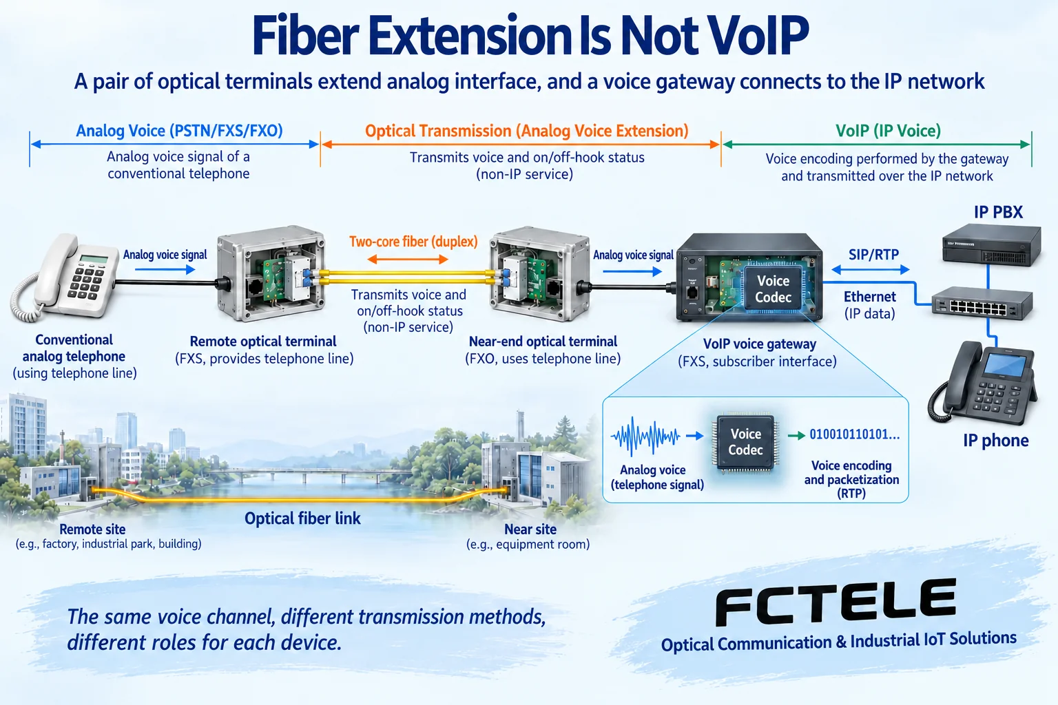
A telephone fiber optic transceiver can extend an analog extension to a remote site, but it does not automatically become a VoIP gateway just because fiber is used. To make an analog phone join an IP telephony system, you need a gateway that truly supports voice encoding, call control, and IP media transport. The customer must first determine: is the goal only to send the line farther, or is the goal to connect telephone service into an IP system? The two things can be combined, but they cannot be confused with each other.
What problems do fiber extension and VoIP each solve?
An ordinary analog phone uses a telephone line to get power, ringing, and a voice channel. A telephone fiber optic transceiver transmits voice and line status between two ends, and restores the telephone interface at the remote end. What it solves is distance, cabling, and transmission environment problems, and the two ends usually need to be paired as a set. The device may use digital encoding internally, but “digital inside” does not mean “IP telephony outside.”
VoIP carries voice over an IP network. A gateway needs to convert analog voice into media data that the network can transport, and it also needs to let the telephone system know who is calling whom, when to connect, and when to release. When a customer already has a network but only has analog phones, a voice gateway with FXS interfaces can be considered. When a customer already has an analog PBX, it is also necessary to confirm whether the connection is an extension port or a trunk port; not all RJ11 interfaces should be treated as the same type of interface.
How is one clear combined solution connected?
Imagine that a factory duty room is far from the equipment room, but the equipment room already has an IP telephony system. You can connect the FXS port of the voice gateway in the equipment room to the FXO port of the near-end telephone fiber optic transceiver, use a paired transceiver to extend the connection, and connect the FXS port of the far-end transceiver to an analog phone. In this way, the gateway still handles IP access, and the transceiver handles sending the analog interface conditions to the remote end. The number of interfaces, port roles, call compatibility, and pairing of the two end devices all need to be checked.
FXS can be understood as the side that provides telephone line conditions, while FXO uses that line. Directly connecting two line-providing ends is not a way to add functionality. Although an ordinary phone usually does not mark FXO on its housing, it uses the line in this connection. If the site has a PBX trunk port, a proprietary digital extension, or a magneto telephone, the design should be redone according to the interface type, and the ordinary analog extension diagram should not be applied.
Another solution is to place a voice gateway at the remote end and connect directly back to the system through the IP network. If the remote end already has reliable Ethernet, this may no longer require a telephone fiber optic transceiver. But network quality, power supply, remote management, and security policies must be checked. Which one to choose is not about which is “more advanced,” but about whether the service endpoints, existing resources, and maintenance capabilities match.
Why are call control and sound two logical paths?
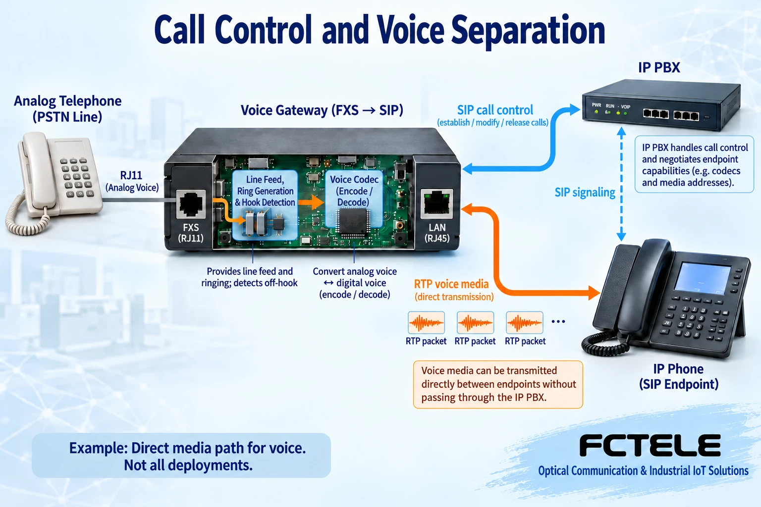
Taking a common SIP system as an example, SIP is the control protocol for establishing, modifying, and ending sessions. It carries call requests, answers, and media negotiation information, and it is not equal to all the sound in a call. The sound is usually carried by RTP. RTP divides the encoded voice into data packets with sequence numbers and timing information, and the receiving end restores playback according to the rhythm. Different deployments may let media travel directly between endpoints, or they may forward it through a server or border device.
Therefore, “it can ring and connect” only proves that part of call control succeeded; it does not prove that media flows in both directions. Incorrect firewall, address translation, routing, or media address negotiation may cause one-way no audio. Conversely, a lit transmission lamp on the fiber optic transceiver also does not prove that the gateway has registered with the IP telephony system or that number routing is correct. Both segments must be tested, and one indicator cannot be treated as the conclusion for the entire call.
How should delay, jitter, and packet loss be understood?
Voice encoding, packetization, network forwarding, and playback buffering all introduce time. Jitter refers to changes in the arrival interval of data packets. The receiving end can use a buffer to absorb a certain amount of change, but a larger buffer also increases waiting time. Packet loss means that some voice information did not arrive. The endpoint may compensate, but it cannot guarantee complete recovery of the original sound. Switching to fiber does not automatically eliminate queuing and congestion in the IP network.
The encoding rate is only part of the voice data; the line also carries protocol headers and link overhead. Concurrent capacity is also affected by gateway ports, processing resources, licensing, and network conditions. You cannot multiply the number of ports by a voice rate and declare that the network is definitely sufficient, and you cannot describe an ordinary telephone fiber optic transceiver as having arbitrary QoS scheduling built in. Whether voice priority, echo handling, or secure transport exists should be checked against the corresponding device and system functions.
The fiber segment has actual loss, and transmit and receive power must be within the range allowed by the device. The telephone side still has copper cabling and power, and may be affected by grounding, surges, poor contact, or cabling interference. The advantage of fiber in resisting electromagnetic coupling does not mean the entire system is absolutely free of interference, and it certainly does not mean zero delay or no maintenance.
Troubleshooting by boundary is more effective than changing many parameters at once.
First connect a normal analog phone directly to the gateway FXS port, and verify registration, dialing, two-way conversation, and hang-up release. If direct connection fails, handle the gateway, number routing, and IP system first, rather than continuing to change the fiber. After direct connection works normally, insert the paired telephone fiber optic transceivers and compare the same number and the same service process; this can narrow down the fault boundary.
If there is no dial tone after inserting the fiber optic transceivers, check the FXS/FXO roles, port correspondence, and line status transmission. If dialing works but the remote end does not ring, separately confirm whether the gateway initiates the corresponding line action and whether the fiber optic transceiver restores that action. When a call connects with one-way no audio, check both the analog voice path direction and the IP media transmit and receive situation; do not conclude from the symptom alone that a particular fiber is broken.
If the voice is intermittent while call status is stable, record whether the problem grows with concurrency, and check IP packet loss, jitter, and resources. Do not disable all firewalls or expose the gateway directly to the public internet just for troubleshooting; have the administrator check the necessary paths and access scope according to the system documentation. Back up the configuration before changes, and change only one condition at a time, to avoid mistaking temporary recovery for the root cause being solved.
From one call to complete acceptance
Record the gateway port, number, near-end fiber optic transceiver port, and far-end phone channel by channel. Test calls in both directions, answering, voice, and hang-up release, then perform multi-channel concurrency under the design requirements. DTMF is the dual-tone multi-frequency signal used during dialing. The gateway and IP system may use different transport methods, and the automated voice menu needs to be verified separately; it cannot be judged only by whether ordinary speech is normal.
Caller ID, fax, network disconnection alarms, and re-registration after recovery must also be accepted according to requirements. Emergency communication when power fails should be designed separately, and ordinary devices should not be assumed to have power-failure bypass. All recovery times, quality indicators, and compatibility conclusions should come from model documentation and site records, without using fabricated improvement ratios.
Feichang Technology products should be placed in the correct link.
Feichang Technology FCP-O16/FCP-S16 desktop telephone fiber optic transceiver The documentation states that FXO connects to the PBX and FXS connects to the telephone, which is suitable as an entry point for checking analog interface extension. This cannot prove that it has SIP registration or RTP gateway capability. When purchasing a VoIP solution, the gateway model, supported protocols, and system compatibility list should be confirmed separately; this article does not transfer other manufacturers’ gateway functions to Feichang Technology fiber optic transceivers.
Documentation note: general interfaces and call procedures reference Cisco analog port documentation, and IP gateway boundary reference Cisco communications gateway documentation. The illustrations are general diagrams, not the internal structure of a specific product or a measured network. This article corrects the original statement that “fiber extension naturally equals VoIP access.”
Translated from the Chinese technical article. Source first published: 2024-11-07. Source last revised: 2026-10-13T13:49:23+08:00. Read the Chinese source
