


Put Functions Back into the Service Path
Different functions in a PCM multiplexer solve different problems. Voice encoding digitizes analog speech, multiplexing organizes various services onto a trunk, time slot cross-connect adjusts channel correspondences, and protection functions change the bearer path under agreed conditions. They can exist in the same device, but not every device is equipped with all of them just because its model number says PCM. To judge functions, you should refer to the specific board, software version, and manual. It is not appropriate to write the capabilities of one series as the standard configuration of all devices.
During maintenance, it is best to first draw two diagrams: one marking telephone ports, service modules, E1 trunks, and remote interfaces; the other marking primary and backup links, device power, and clock sources. The first answers “where is this service delivered?” and the second answers “how will it continue to be carried after a fault?” Mixing these two relationships can lead to mistaking channel adjustment for fault switching, or treating a backup line as additional service capacity.
Time Slot Cross-Connect Adjusts Channel Correspondences
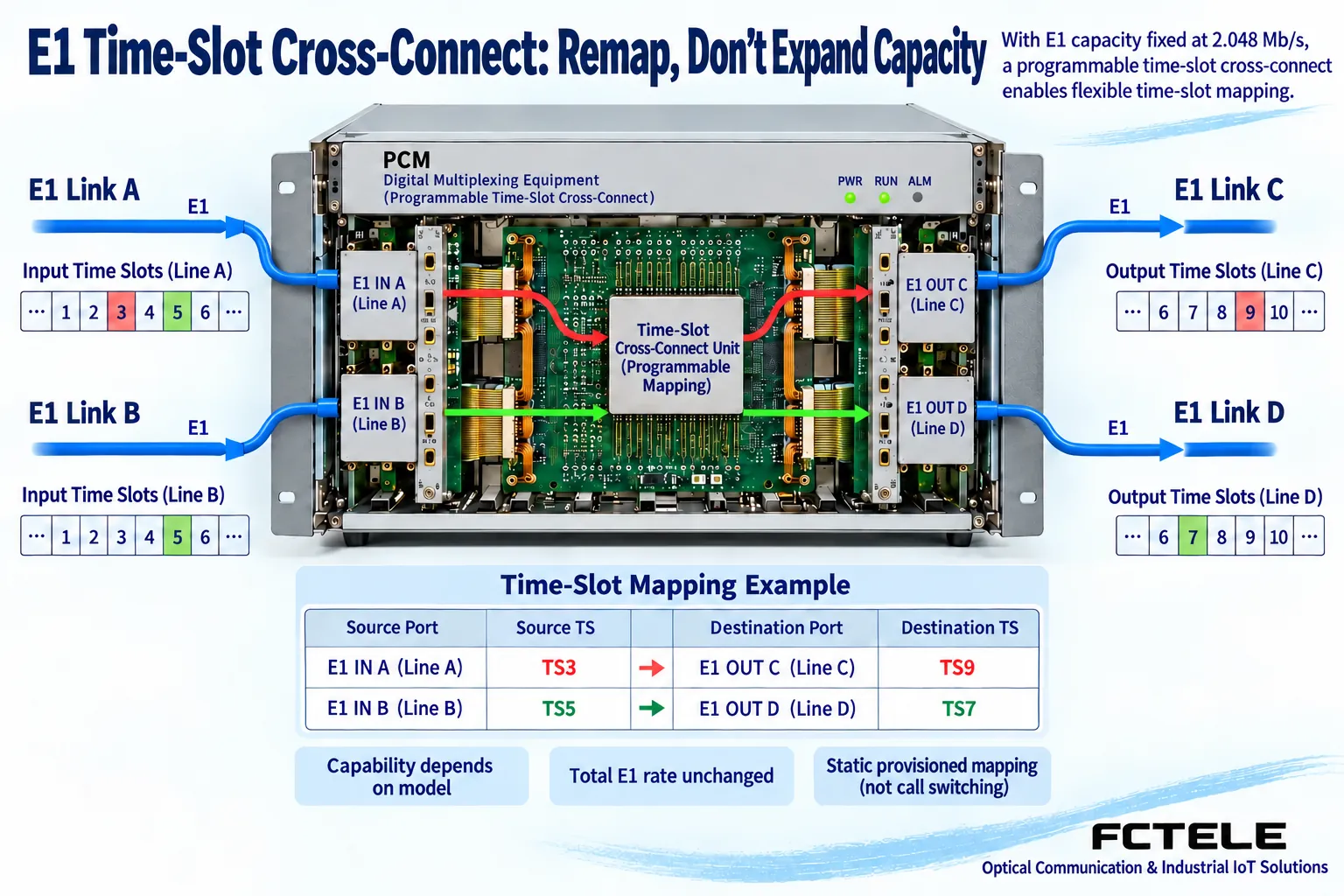
In a fixed multiplexing scheme, local ports correspond to agreed trunk time slots. A device with the appropriate cross-connect capability can, according to configuration, connect a certain input time slot to a specified output time slot. For example, within the supported configuration range, connect input TS3 to output TS9, and at the same time connect another channel TS5 to TS7. This is only an example to illustrate position mapping. The actual cross-connect range, cross-E1 capability, and signaling handling must be confirmed by the selected model.
After the mapping is changed, the far end must use the new correspondence table to restore services. If only the local end is changed without synchronously adjusting the far end, line synchronization may still be normal, but misconnection or inability to make calls may occur. Channel cross-connect also does not increase trunk bit rate; moving a service to another position cannot make the same E1 carry more independent data out of thin air. Without documentary support, it is even more inappropriate to describe cross-connect as being able to arbitrarily copy services or broadcast to multiple ports.
Channel Cross-Connect Is Different from Program-Controlled Switching
A program-controlled switch establishes and releases connections based on numbers and call states, and also handles corresponding user management. PCM time slot cross-connect is usually a channel mapping configured by engineers. You cannot assume that a device can dynamically route based on dialing just because it has a cross-connect function. A device can handle voice encoding and corresponding signaling, but whether it has independent call control depends on explicit product functions. It cannot be inferred from the similar words “switching” and “cross-connect.”
For example, when extending the extension lines of a PBX, the PCM device is responsible for delivering the services of each user port to the remote end, while numbers and outside line privileges are still managed by the PBX. Adjusting the time slot table can change which line connects to which remote telephone, but it will not automatically add extension numbers. When testing the cross-connect function, you should check ringing, conversation, and release along the port table; when testing numbers or dialing rules, you should check in the system that actually handles call control.
The Purpose of Dual E1 Protection Is Not Capacity Expansion
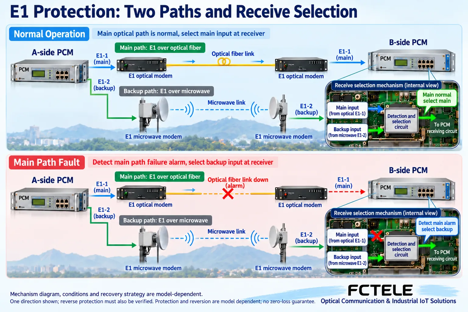
A protection scheme usually gives the same group of services two available bearer paths, and the device selects one of them under agreed trigger conditions. In contrast, a capacity expansion scheme can assign two E1s to different services separately. Both types of devices may have two E1 ports, but they have different capacity definitions. You cannot advertise two lines used for primary and backup as double the number of independent services, nor can you assume that any dual E1 chassis supports automatic protection.
Feichang Technology FC2C-E1O30/FC2C-E1S30 public materials list 30 telephone lines and a dual E1 protection arrangement, which can serve as a model entry point for checking such requirements. However, the protection description in the materials should be further translated into acceptable conditions: whether the trigger is loss of signal, synchronization abnormality, or another event; how it determines that the backup is available; and whether it uses automatic return or manual selection after recovery. Do not write the continuity description in promotional materials as meaning that not a single sample is lost under all conditions.
Primary and Backup Lines Also Need Independent Conditions
If two E1s pass through the same transmission chassis, the same power supply, or the same vulnerable cable path, one fault may affect both primary and backup at the same time. The number of protection ports does not equal path independence. During design, you should identify shared transmission equipment, power supply, wiring, and equipment room conditions, and explain exactly which segment this protection covers. For example, protecting against trunk interruption does not automatically cover a local PCM device power failure or a telephone board failure.
The backup channel should have matching framing, time slot, and signaling arrangements, and should actually be able to establish the correct services when needed. Clock sources should also be included in the check: after switching the bearer, the receiving device may use a different timing source. If the configuration is not coordinated, slips may still occur after the line recovers. Matching primary and backup parameters does not mean that all devices must use internal clocks at the same time; rather, the complete timing relationship must meet the actual network requirements.
How to Test Switching and Recovery
First complete a service baseline test on the normal path, recording port mappings at both ends, alarm status, and clock sources. Then, within an approved test window, use the method supported by the manual to simulate the agreed fault, and observe backup selection, alarm changes, and actual telephone service behavior. Whether the voice in an ongoing call is interrupted, whether a new call can be established, and whether it can be released after hanging up should all be recorded independently. You cannot just observe whether the port light has changed color.
After restoring the primary line, verify whether the actual policy matches the configuration, including whether it returns, what conditions are required, and whether there are any service abnormalities during return. Do not judge protection to be complete just by testing that “pulling the primary line causes switching.” Abnormalities on the backup line itself, simultaneous failure of both lines, and different recovery sequences may produce different behavior. Switching time or service impairment requires corresponding measurement methods and model basis. Without measurement, “instantaneous” or “lossless” cannot be used as acceptance conclusions.
Loopback and Bit Error Tests Each Have Boundaries
Interface loopback helps narrow down the fault scope, but the loopback location and the links it covers should be noted. For example, a loopback near the local device cannot prove that the remote telephone port is normal, and an E1 trunk loopback cannot replace actual voice and signaling acceptance at both ends. Bit error results should record the test path, duration, pattern, and service conditions at the time. A short period with no bit errors does not prove that all clock switching and intermittent abnormalities have been ruled out.
Testing may affect normal services and must be arranged according to the manual and on-site maintenance rules. During recovery, confirm that loopback is removed, port mapping is restored, and alarms are cleared, then check real user calls. Maintenance records should preferably list line-layer and service-layer results separately: the line layer focuses on signal, framing, and bit errors; the service layer focuses on correct ports, two-way voice, and signaling. In this way, when the next fault occurs, you can know what has been verified before.
Keep Recoverable Configurations and Acceptance Records
Before changing time slots, save the original mapping and device configuration, and attach consistent labels to each trunk and telephone line. After changes, confirm channel by channel so that errors can be restored according to the original table, avoiding the inability to distinguish causes after adjusting multiple links at the same time. Records should include device models and versions at both ends, board positions, input and output time slots, primary/backup definitions, and clock arrangements; a screenshot of only one chassis cannot explain the complete service path.
The function list should clearly separate confirmed items, optional configurations, and conditions still to be tested. Confirm model capabilities during procurement, check actual configurations during installation, and leave real service results during acceptance, so that the three correspond to each other. Time slot cross-connect makes channel organization more flexible, and primary/backup protection improves availability under agreed fault conditions, but they are still limited by interfaces, capacity, and shared fault points. Understanding these boundaries is what allows the functions to work on site.
Documentation note: The principle diagrams have been checked against technical content and are used to explain general mechanisms. They are not product photos or measured records. Specific interfaces, modes, and capabilities are subject to the selected model, version, and on-site verification.
Reference materials: ITU-T G.704: Frame structures for digital interfaces
ITU-T G.703: Electrical characteristics of digital interfaces
FC2C-E1O30/FC2C-E1S30 product documentation
Translated from the Chinese technical article. Source first published: 2021-07-01. Source last revised: 2026-10-13T13:23:07+08:00. Read the Chinese source
