


First describe the symptoms, and do not rush to replace the whole unit
A PCM service problem may appear as all channels down, a single channel with no voice, ringing on the wrong port, intermittent breaks, or boards that repeatedly fail. These symptoms do not necessarily have the same cause. Record when the problem happened, what was affected, what alarms the equipment showed, and what was recently changed, then decide which layer to check. Without records, changing cables, changing clocks, and adjusting ports at the same time may restore service temporarily, but it becomes hard to explain the cause or prevent it from happening again.
Troubleshooting can be divided into four layers: power and electrical conditions, E1 signal and framing, channel mapping, and service interfaces. When all channels are abnormal at the same time, first pay attention to the shared power, trunk, and timing conditions; when only one channel is abnormal, first compare that port, its wiring, and its mapping. This order helps narrow the range; it is not an absolute fault judgment, and the specific alarm descriptions for the model and on-site testing are still needed.
Normal power cannot be judged by one indicator light alone
First, qualified personnel should check the power type, allowed range, polarity, and connection status according to the manual. A lit power light does not guarantee that all boards and internal power conditions are correct; DC is also not a safety guarantee that “usually nothing will burn out.” Voltage mismatch, wrong polarity, abnormal surges, or interfaces being exposed to external electrical conditions can all cause damage. If there is already a burning smell, abnormal heat, or visible damage, do not keep repeatedly powering it on for tests.
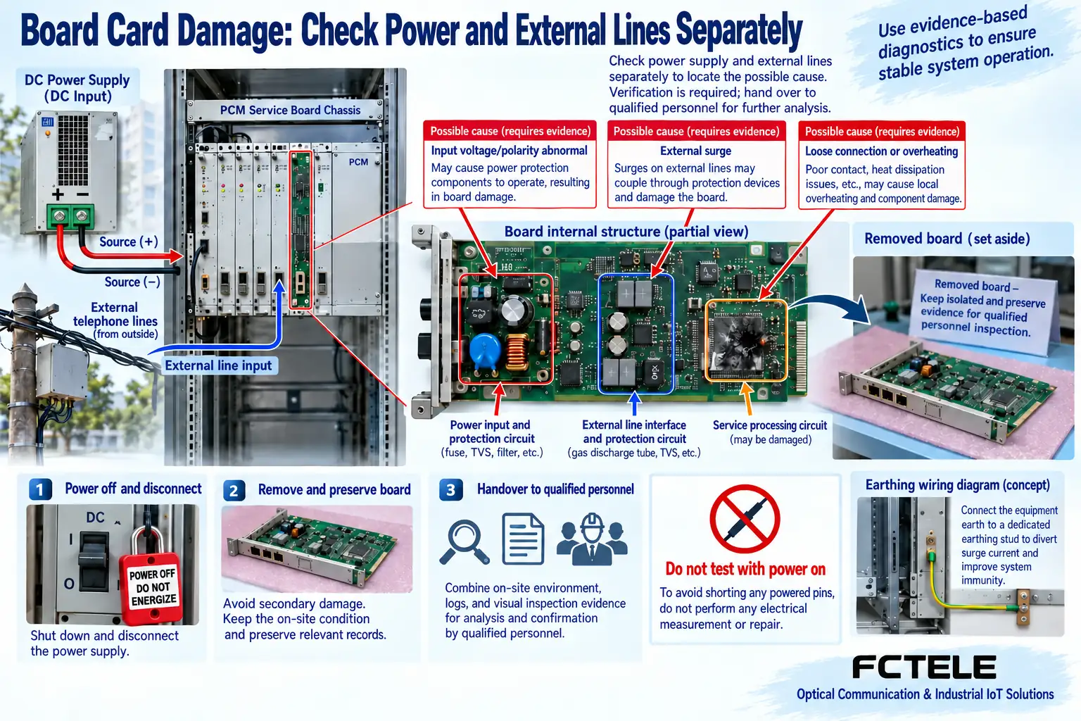
Shut down, isolate, and contact the appropriate maintenance personnel according to on-site rules, and keep the faulty board, model, and conditions under which it occurred. This article provides a way to organize causes and locate problems; it is not a guide for live probing, internal repair, or protective grounding modification. Before replacing a board, confirm that possible external causes have been handled; otherwise, if the new board is damaged again, it does not prove that all products of the same model have quality problems. It may also be the same abnormal electrical condition acting again.
No E1 signal and no synchronization are different
When the line does not receive a valid signal, check the corresponding transmit and receive directions, cable continuity, connectors, and intermediate transmission equipment. E1 electrical specifications need to match; conditions such as 75Ω coaxial and 120Ω balanced cannot be mixed, and an RJ45 shape does not mean Ethernet. Alarm abbreviations and indicator light colors are based on the specific model manual; you cannot apply one red-green light judgment table to all equipment.
If a signal is received but frame synchronization cannot be established, continue checking framing, line coding, time slot and signaling settings, and whether intermediate equipment transmits transparently or adapts the signal as needed. Successful line synchronization only means that the relevant line-layer conditions are met; it does not mean that all telephone channels are correct. First distinguish between missing signal, synchronization abnormality, and service failure, to avoid skipping the remaining problems just because one light is on.
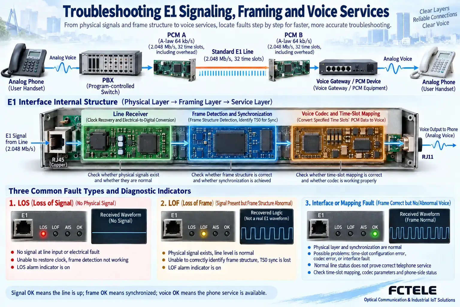
For intermittent breaks, check timing and statistics
If the line can be established but voice breaks, errors, or abnormal releases occur from time to time, check the time relationship between alarms and statistics, and verify the complete clock source. A master-slave conflict at the two ends or a timing loop may cause slips; intermittent changes in power, connectors, and the external environment may also affect service. Do not conclude that the problem is solved just because one restart restored it.
During inspection, also record the trunk, transmission equipment, and PCM chassis parameters, and make clear which unit provides the clock, which unit recovers the clock, and whether the abnormality occurs after a primary/backup switchover. Testing should cover enough actual service conditions and record the duration and results according to the specified method. A fixed line rate does not mean that the system’s end-to-end delay necessarily meets all service requirements; the nominal E1 rate cannot replace measurement of the actual abnormality.
Locate wrong connections, one-way voice, and no ringing separately
If ringing reaches the wrong telephone, check the mapping table along the local port, E1 channel, and remote port, and see whether the time slot cross-connection was recently adjusted or a board was replaced. If a call can be made but voice is present in only one direction, check the transmit and receive paths, subscriber line, and module parameters separately. You cannot assume that a single-channel problem must be the telephone itself just because the trunk has no alarm.
When there is no ringing or a call cannot be released, check the FXS/FXO roles and signaling compatibility. A switch subscriber port is usually FXS, the local extension interface needs to match FXO, and the remote FXS connects to an ordinary analog telephone. Hotline or other special modes are handled according to the model instructions. PCM does not automatically manage numbers and outside line permissions; if only dialing an outside line fails, you should also check the switch policy that actually handles call control.
Loopback can narrow the range, but it cannot replace acceptance testing
A loopback test must state its location. A near-end interface loopback may be used to verify the path from the local unit to that point; a farther loopback can cover the intermediate transmission section, but it still may not cover the remote telephone port and signaling. One loopback with no errors cannot lead to the conclusion that the entire link, all modules, and real calls are normal. Locating section by section according to the test methods supported by the model is more useful than vaguely writing “loopback is normal, so the equipment has no problem.”
When testing will affect services, arrange a maintenance window, save the test configuration, and exit loopback after finishing. After restoring the line, retest real telephone or data services to confirm that no test codes, temporary mappings, or wrong clock configurations are left behind. In the acceptance record, write clearly what was covered and what was not tested, so that the next time an abnormality occurs, a partial result will not be mistaken for an overall system conclusion.
Repeated board burning requires checking common external conditions
When boards are repeatedly damaged, compare the power, subscriber lines, trunk, installation location, and environment used each time, and look for common conditions. Incorrect power supply, surges coupled from external lines, incorrect interface connections, abnormal contact, or heat dissipation problems all need to be checked by professionals according to the documentation. You cannot rule out electrical causes just because the power is DC, and you cannot directly attribute it to another party’s product or some raw material without evidence.
Before replacing a board, keep the damaged position and the fault process, and if necessary have the manufacturer inspect the faulty board. The surge tolerance or protection level of the equipment should have a clear model basis; an unverified high voltage value cannot be written as a general capability of all PCM chassis. Protective grounding and protective devices must also conform to the overall on-site design; changing them arbitrarily may create new risks. Troubleshooting conclusions should be based on actual inspection, not guesswork.
After recovery, verify services and save the conclusion
After finding a suspected cause, make only one traceable adjustment at a time, and record the conditions before and after the adjustment. After recovery, verify channel-by-channel mapping, ringing, two-way voice, release, and the agreed concurrent quantity, and observe line alarms and statistics. If primary/backup protection is configured, then confirm that switchover and recovery behavior match the settings; acceptance cannot end just because a new board powers on or a fault light goes out.
The final record includes symptoms, affected range, inspection path, evidence, handling, and recovery testing. When the cause is still not determined for the time being, clearly state the conditions that still need observation, rather than giving a “permanently solved” conclusion. Verifying power and electrical conditions, trunk timing, channel mapping, and service interfaces separately can reduce unnecessary parts replacement and also avoid mixing repeated damage, wrong connections, and insufficient capacity into the same category of PCM fault.
Documentation note: The principle diagrams have been checked against technical content and are used to explain general mechanisms; they are not product photos or measured records. Specific interfaces, modes, and capabilities are subject to the selected model, version, and on-site verification.
Reference materials: ITU-T G.703: Electrical characteristics of digital interfaces
ITU-T G.704: Frame structures of digital interfaces
Feichang Technology E1 PCM multiplexer
Translated from the Chinese technical article. Source first published: 2021-06-21. Source last revised: 2026-10-13T13:23:07+08:00. Read the Chinese source
