


First write the service requirements as a wiring table for both ends
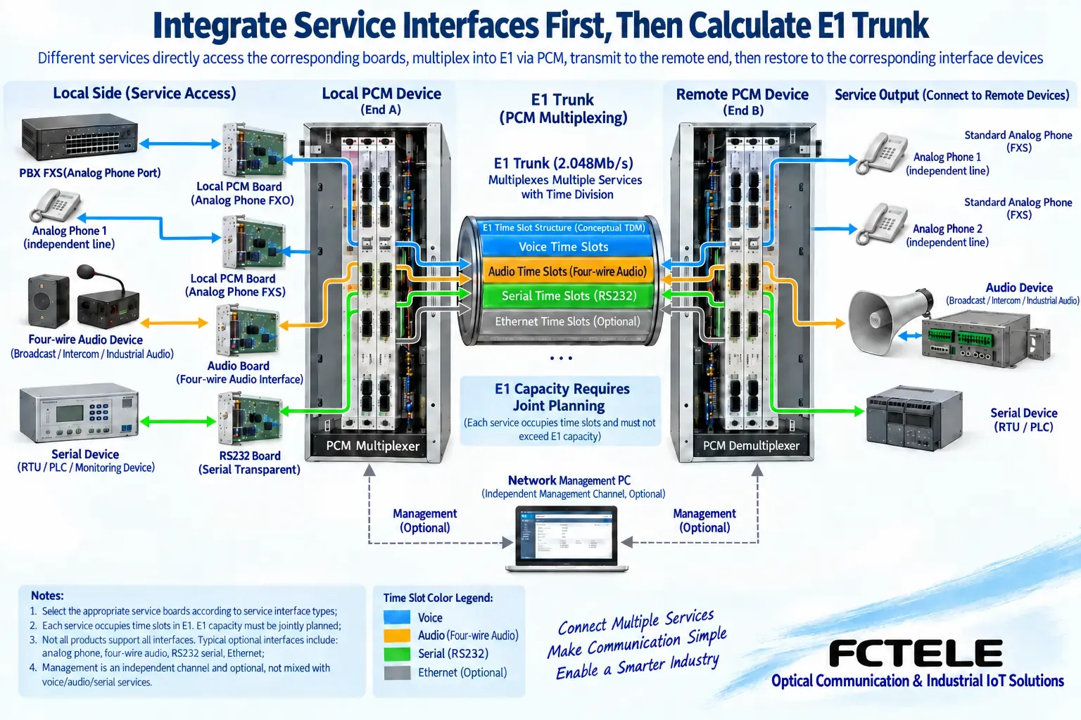
The value of a PCM integrated access device is to aggregate multiple services supported by the device onto an agreed digital trunk. Whether it suits a project first depends on the interfaces that both ends actually need to connect, not on how many industries are listed in promotional materials. The requirements table should state the device source, port role, signal type, quantity, and remote destination. For example, switch analog extensions, four-wire audio, and low-speed serial ports are three different access requirements and cannot be replaced by “how many communication channels are needed.”
Even when both are called telephone services, some need to extend switch subscriber lines, while others use dedicated hotlines; even when both are called data services, some send serial bytes, while others need Ethernet frames. Before purchasing, provide the existing device interface information and wiring relationships first, then let the supplier confirm the boards, configurations at both ends, and bearer mode. A management network port on the chassis cannot be directly counted as a service Ethernet port, and a serial management interface is not equivalent to a module that can transmit user serial data.
Even if the interfaces are the same, verify roles and signals
Ordinary analog telephones usually connect to FXS interfaces, while analog subscriber ports on a switch usually connect to matching FXO interfaces. FXS provides line functions such as power feeding and ringing, while FXO takes the corresponding subscriber-side role. Connecting two ports that both provide power feeding, or ignoring the module roles at both ends, can cause call setup failure and even impose electrical conditions that should not be endured. The purchasing table should preferably directly mark “the end connected to the switch” and “the end connected to the telephone,” and confirm them from model documentation.
For four-wire audio interfaces, confirm input and output direction, impedance, and level range; for RS232 and RS485, verify the electrical standard, terminals, and data parameters. Because they use the same screw terminals, do not interchange audio cables, serial cables, and telephone cables. Integrated access means the device is equipped with the corresponding access modules and channel mechanisms; it does not mean different signals are automatically recognized or arbitrarily converted.
Port count and simultaneous service count must be separated
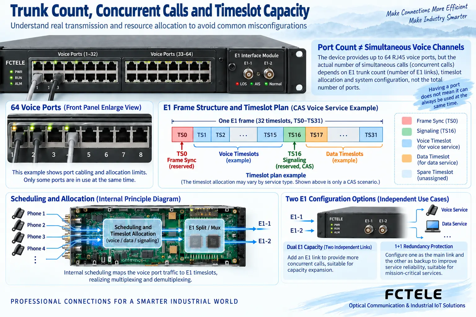
The framed E1 line rate is 2.048 Mbit/s, and a typical frame consists of 32 time slots. In common channel-associated signaling telephone solutions, TS0 carries frame synchronization and TS16 carries signaling, while the remaining 30 time slots are used for voice. Therefore, “how many subscriber ports the chassis has,” “how many telephone calls can be connected simultaneously,” and “how many E1 trunks are used” must be listed in separate columns. An increase in the number of modules does not mean the capacity of a single trunk can increase without limit.
Some models use dynamic allocation, assigning more subscriber ports to limited channels according to actual calls. Feichang Technology FCC-E1O64/FCC-E1S64 product documentation lists 64 telephone ports, single E1, and up to 31 simultaneous calls. This is the specific mechanism of that model and should not be applied to ordinary 30-channel fixed-channel devices. Conversely, because a model is marked with 64 channels, do not promise 64 simultaneous calls. Purchasing should confirm the behavior when concurrent capacity is exceeded and the actual demand during service peaks.
Multiple trunks may expand capacity or may be used for protection
Two E1 lines do not necessarily mean service capacity is doubled. Some devices let the two trunks carry different channels separately to increase total service volume; others place the same group of services on primary and backup lines and switch the bearer when an abnormality occurs. The goal of the latter scheme is protection, and the backup line cannot be counted again as independent service capacity; otherwise, quotations and actual on-site capability will differ.
For example, public documentation for Feichang Technology FCC-E2O60/FCC-E2S60 lists 60 telephone lines and two E1 lines; FC2C-E1O30/FC2C-E1S30 lists 30 telephone lines and a dual-E1 protection arrangement. Both mention “two E1 lines,” but their purposes differ. Specific port mapping, board versions, and protection actions must continue to be checked in the manual and verified. Chassis model, service capacity, and protection method should be written separately in the purchasing list and cannot be summarized with one phrase, “supports dual E1.”
Time slots, coding, and clocking require coordination at both ends
When one end places a certain service into a specified time slot, the opposite end must deliver the same channel to the correct interface. If the coding, framing method, signaling, and channel mapping at both ends do not match, the line may already be established while the telephone still cannot work normally. Integrated services also occupy different amounts or modes of resources, and it cannot be assumed that all boards calculate one voice time slot per channel.
The network diagram should also indicate the clock source. E1 provided by an operator, existing transmission equipment, and local multiplexing equipment may have different timing requirements; an inappropriate master-slave configuration can cause slips or instability. During the purchasing stage, the complete link should be reviewed by technical personnel to confirm which device provides or recovers timing and whether the source changes after failover. Comparing only the number of telephone ports will miss these important conditions that determine interoperability.
Clarify the boundaries of E1 electrical ports, optical ports, and IP bearer
E1 electrical ports should match the actual specification, such as 75Ω coaxial or 120Ω balanced, and the transmit and receive directions and cable terminals must also correspond. The appearance of RJ45 does not mean Ethernet. If an E1 PCM device does not have the corresponding optical transmission function, it cannot be directly connected to fiber; a matching external E1 optical transmission device is required. Integrated devices with optical ports must also have the optical parameters and transmission protocol at both ends checked; do not assume that optical modules with the same interface can interoperate.
If the line passes through an IP network, confirm whether the device supports the corresponding circuit emulation, buffering, and clock recovery. An ordinary Ethernet network port or VPN connection by itself cannot turn an E1 service into a usable transparent circuit. Management connections are used for configuration, monitoring, and alarms; they may share the chassis but should be considered separately for access permissions. Service bearer, management communication, and physical media should be marked with different lines in the drawing.
Choose chassis and modules according to maintenance method
On site, consider power supply specifications, installation space, heat dissipation, grounding conditions, module maintenance, and spare parts arrangements. Interface options, network management functions, or chassis compatibility in product documentation must correspond to the actual purchased version, and all configurations of a series cannot be written into the acceptance terms for one device. For example, desktop low-channel devices and rack-mounted integrated devices each have their own conditions for installation and maintenance and should be selected according to real needs.
Feichang Technology FCC-E1O16/FCC-E1S16 documentation provides a low-channel E1 telephone multiplexing option and can serve as an entry point for model verification when accessing a small number of subscriber lines. For multi-service chassis, also list each board, slot, port assignment, and spare configuration. When SNMP or console maintenance is required, confirm the specific version, readable parameters, and alarm outputs, rather than judging complete functionality only from the product title.
Replace parameter stacking with scenario-based acceptance
Assume a warehouse needs to extend 12 extensions, expects 6 to be used simultaneously, and also has two serial ports. First confirm the telephone interface pairing and serial module support separately, then check whether trunk resources are sufficient, and finally connect real service devices at both ends for testing. This example explains a method for organizing requirements; it does not mean that any 12-line telephone PCM device supports serial boards, nor does it replace the supplier’s actual configuration confirmation.
Acceptance should cover per-channel mapping, two-way calls, concurrent calls, serial transmission and reception, timing stability, and the agreed exception handling. If primary-backup protection is purchased, further record fault triggering, service behavior during switching, and recovery strategy; if only a single trunk is purchased, protection should not be written as a default function. The final list should enable installers to wire according to the table and maintenance personnel to locate according to the drawing, with quantities, interfaces, and bearer conditions checked item by item.
Documentation note: The principle diagrams have been checked against technical content and are used to explain general mechanisms; they are not physical product photos or measured records. Specific interfaces, modes, and capabilities are subject to the selected model, version, and on-site verification.
Verification materials:ITU-T G.704: Frame structures for digital interfaces
ITU-T G.703: Electrical characteristics of digital interfaces
Feichang Technology E1 PCM multiplexing equipment
FCC-E1O16/FCC-E1S16 product documentation
FCC-E2O60/FCC-E2S60 product documentation
FCC-E1O64/FCC-E1S64 product documentation
FC2C-E1O30/FC2C-E1S30 product documentation
Translated from the Chinese technical article. Source first published: 2024-09-24. Source last revised: 2026-10-13T13:19:24+08:00. Read the Chinese source
