


SFP and SFP+ mainly describe the packaging and interface system of pluggable modules; CWDM and DWDM describe how to arrange optical wavelengths so that multiple optical channels share a fiber. They are not two mutually exclusive product categories of “short-distance transceivers” and “long-distance transceivers.” A module can be both an SFP package and a CWDM optical interface, while distance must be considered separately based on transmit, receive, cable, and line conditions.
First, distinguish: a complete unit, a module, and a fiber line are not the same object
In the field, people call a small box with a power supply, network ports, and optical ports a “fiber optic transceiver,” usually meaning a complete Ethernet media conversion unit. It sends compatible Ethernet traffic from the copper side to the fiber side, and some also have switching, management, or fault relay functions. A complete unit may use a fixed optical interface or may have a module slot. Whether it has these functions must be checked in the unit’s documentation and cannot be inferred from the name of an optical module.
SFP is a small pluggable module system. A common optical module is plugged into a slot in a switch, router, or other compatible host, and uses the power and electrical interface provided by the host to perform optical transmission and reception. It is not a transceiver with its own RJ45 network port, power supply, and complete forwarding function, nor is it a fiber connector that works by shape alone. A fiber line includes optical cables, patch cords, connectors, splice points, and possibly WDM components; all three must be checked together.
Inside the module, how electricity and light are converted
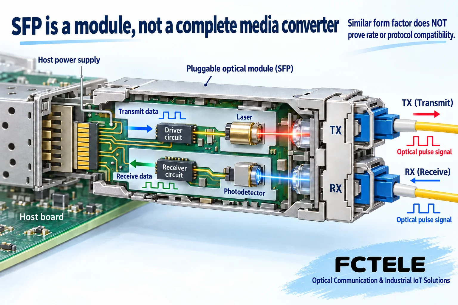
When transmitting, the host delivers an electrical signal that meets the interface requirements to the module. The driver circuit controls the light source to form an optical signal carrying data, which is sent into the fiber through the TX transmit port. When receiving, light from the far end enters the RX receive port, and the detector converts it into current, which is then processed by the receive circuit and delivered to the host. The upper and lower paths in the figure explain transmission and reception respectively; they do not mean two unrelated services.
How characteristics such as light intensity change with data depends on the specific interface standard. The pulses in the figure help with understanding, but this simplified waveform cannot be generalized to all high-speed modules. A module also does not automatically turn 100 Mbps traffic into 1 Gbps traffic, or translate Ethernet into telephone or serial protocols. If the protocol, encoding, and host electrical interface do not match, communication will still fail even if the mechanical dimensions are the same.
Why SFP and SFP+ cannot be used to judge distance
A similar metal shell only helps identify the mechanical form; it cannot tell you the light source power, receive capability, or allowed line loss. SFP is commonly used for Gigabit and similar interfaces, while SFP+ is commonly used for 10 Gigabit and similar interfaces, but the actual rate and supported protocols must be confirmed jointly from both the module and host documentation. Whether the host supports lower-rate modules and whether it can recognize a specific module code cannot be judged only by the slot shape.
The same package can have multimode, single-mode, different wavelength, and different optical budget versions. Therefore, “SFP only does short distance” is not true; conversely, being labeled DWDM does not guarantee communication across a city or even across countries. Long-distance systems may also require amplification, regeneration, dispersion and noise analysis, and other design work. The nominal distance of one module cannot replace the plan for the entire line.
Why WDM allows multiple channels to share a fiber
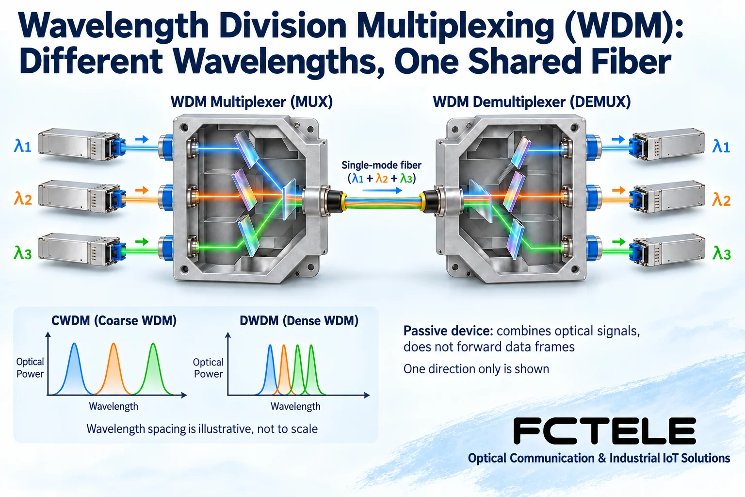
Wavelength division multiplexing uses the condition that light of different wavelengths can transmit in the same fiber core. Each transmit module first generates light that meets the requirements of its own channel; the multiplexer combines them into a common optical port according to wavelength. The remote demultiplexer then directs different wavelengths to the corresponding channels and delivers them to the receiving equipment. It processes the optical path, rather than first reading Ethernet frames and then forwarding them by IP address.
Figure 2 shows one direction in which three channels share a section of fiber core. A complete bidirectional link also requires designing the reverse channel, for example by using another fiber core, or by arranging complementary wavelengths in a supported single-fiber solution. The TX and RX wiring of ordinary dual-fiber modules, the wavelength pairing of single-fiber bidirectional modules, and the WDM planning of multiple service channels are three related but different things, and “one fiber” cannot be used to confuse them all.
The difference between CWDM and DWDM is not just one more letter in the name
CWDM is coarse wavelength division multiplexing, and DWDM is dense wavelength division multiplexing. The main difference involves the arrangement of wavelength channels and the corresponding optical system requirements. You can think of channels as different positions, but this analogy cannot be extended to mean that any modules can be interchanged. The module’s center wavelength, allowed deviation, and the WDM channel range must match, and the receiving end must also support the signal after passing through that line.
Cisco public materials include both CWDM SFP and DWDM SFP, which exactly shows that “package” and “WDM method” can be combined. These materials are used here only to verify concepts, and their channel counts, distances, or compatible host lists are not treated as Feichang Technology product capabilities. Nor should it be assumed that DWDM is naturally more suitable than CWDM for all projects; fiber core resources, number of service channels, line loss, maintenance conditions, and equipment cost all affect the choice of solution.
With WDM, why recalculate the optical budget
Passive multiplexers and demultiplexers do not need power to perform their optical path function, but they introduce insertion loss; connectors, splice points, and optical cables also consume optical power. When estimating received power, subtract the loss of the entire path from the transmit power, then compare it with the receive sensitivity and overload upper limit. Each direction and each channel must be checked, not just the shortest path.
For example, if a campus already has insufficient fiber cores and needs to add several independent links, you can first evaluate whether suitable wavelength modules and WDM components are available. After using a common fiber core, each host port still has its own rate boundary, and it will not automatically become a higher-rate port just because another wavelength is added beside it. A break in the common cable may also affect multiple services at the same time, so this common failure point should be included in redundancy design.
When choosing a Feichang Technology unit, look at the actual interface first, then ask about module support
The Feichang Technology B series category provides complete unit examples of ordinary Ethernet fiber optic transceivers. Among them, the “1 optical 4 electrical Gigabit Ethernet (external power supply)” details list a combination of optical ports and multiple electrical ports, suitable for checking around port count and centralized access needs. However, the optical interface parameters on that page list FC/SC, so it cannot be claimed on that basis that it has an SFP slot, and even less can it be directly claimed to support CWDM or DWDM modules.
The electrical port rate description on that product page also has different expressions, so when ordering, the current specification sheet for the corresponding order number should be requested. If the site truly needs pluggable modules or WDM, the unit slot, available rates, supported module list, and environmental conditions should be confirmed separately. The currently cited category and details are not enough to prove that Feichang Technology provides a certain WDM system, so this article does not fabricate its wavelength configuration, temperature grade, or cross-brand compatibility promises.
How to troubleshoot layer by layer on site
First record the host model and software version, module order number, interface standards and wavelengths at both ends, then draw the complete optical path from TX to the remote RX. Then confirm the WDM channel labels, fiber type, connector endface, and optical budget one by one. During testing, first establish a baseline with a known compatible simple link, then add WDM and the actual cable according to the plan, changing only one condition at a time, to avoid being unable to determine the cause after simultaneously changing equipment and patch cords.
Do not look directly at optical ports or fiber ends, and do not use “seeing red light” to judge the operating wavelength; use tools suitable for the site light source for cleaning and measurement. Modules that support digital diagnostics can provide status information, but displayed optical power does not equal qualified service. Finally, verify errors, packet loss, continuous operation, and recovery process under the agreed load, and save the wiring diagram and channel records. The endpoint of correct classification is being able to explain what each component is responsible for and where the limits are, rather than filling a purchase order with a string of abbreviations.
References:Cisco CWDM SFP solution material and Cisco DWDM SFP material are used to verify the relationship between packaging, wavelength modules, and passive optical paths, and do not indicate that Feichang Technology supports their product configurations;Feichang Technology B series category and 1 optical 4 electrical external power supply unit details are used to confirm the complete unit object and the boundary of interface evidence. The illustrations are general scientific diagrams, not product photos, measurements, or specific model specification drawings.
Translated from the Chinese technical article. Source first published: 2023-11-06. Source last revised: 2026-10-13T12:28:34+08:00. Read the Chinese source
