


An RS-485 hub is used to split one serial communication direction into multiple electrical segments, suitable for situations where instruments are scattered across different floors, workshops, or control cabinets. It is not simply twisting several wires together, and it is not an Ethernet switch. Only by understanding the three steps of receiving, re-driving, and returning the response can you correctly arrange branches, termination resistors, and station addresses.
How RS485 repeaters and hubs correspond
Both a two-port RS485 repeater and a multi-channel RS485 hub can receive serial levels, decide the bits, and then re-drive another electrical segment. A two-port repeater focuses on splitting one line into two segments, front and back, while a multi-channel hub focuses on splitting the upstream direction into multiple independent branches. They are related physical-layer extension devices, but a two-port product cannot be treated as a four-channel or eight-channel branch device. When choosing, first draw the line diagram, then confirm whether you need series extension or multi-direction branching.
“Optical isolation” usually describes the isolation coupling inside the device; it does not mean the site must be connected by fiber. Fiber-optic serial extension devices also require checking the optical interface, fiber type, and pairing at both ends; you cannot connect it as a copper-wire RS485 repeater just because of the name. RS422 and RS485 may also differ in their transmit/receive wire pairs and duplex mode, and only interface modes explicitly supported by the manual can be switched. Isolation does not mean withstanding all interference, regeneration will not correct messages that have already been misjudged, and there is no such thing as zero delay or unlimited cascading that can be promised apart from the model.
1. It splits the line, not the communication protocol
RS-485 specifies the electrical conditions for drivers and receivers. The common two-wire method uses a twisted pair to carry a differential signal: the receiver judges the voltage difference between the two wires, rather than treating one of them as an ordinary power ground. The twisted-pair structure makes external interference act on both wires as equally as possible, but the anti-interference capability of differential reception has limits, and this cannot be used as a reason to omit grounding design or to route signal cables against power cables.
Protocols such as Modbus RTU specify addresses, messages, and checks on top of this electrical interface. A hub usually transmits serial bits transparently; it does not need to understand whether a byte represents temperature or a meter reading, and it will not automatically assign addresses to instruments. After connecting it to the system, the master software and the slaves must still use consistent baud rate, data bits, parity, and stop bits. Transparent forwarding cannot translate two incompatible protocols.
2. The input is judged, then sent out by another set of drivers
After the master request reaches the upstream receiver, the analog differential voltage is judged into digital levels. Internal direction control logic makes the downstream drivers output the corresponding bit sequence at the appropriate time, so each branch has its own driving source. The output waveform can regain suitable levels and edges, but if the input has already been misjudged, the wrong bits may also continue to be forwarded. A repeater cannot be described as universal error correction.
When a slave responds, the direction reverses: the receiver on the corresponding branch reads the response, and the device sends it back to the master through the upstream driver. Two-wire half-duplex means that multiple nodes on the same electrical segment cannot all try to transmit at the same time. Automatic direction control is responsible for switching the circuit’s transmit and receive states, while master polling and slave response rules are responsible for preventing multiple devices from responding at the same time. These two things cannot replace each other.
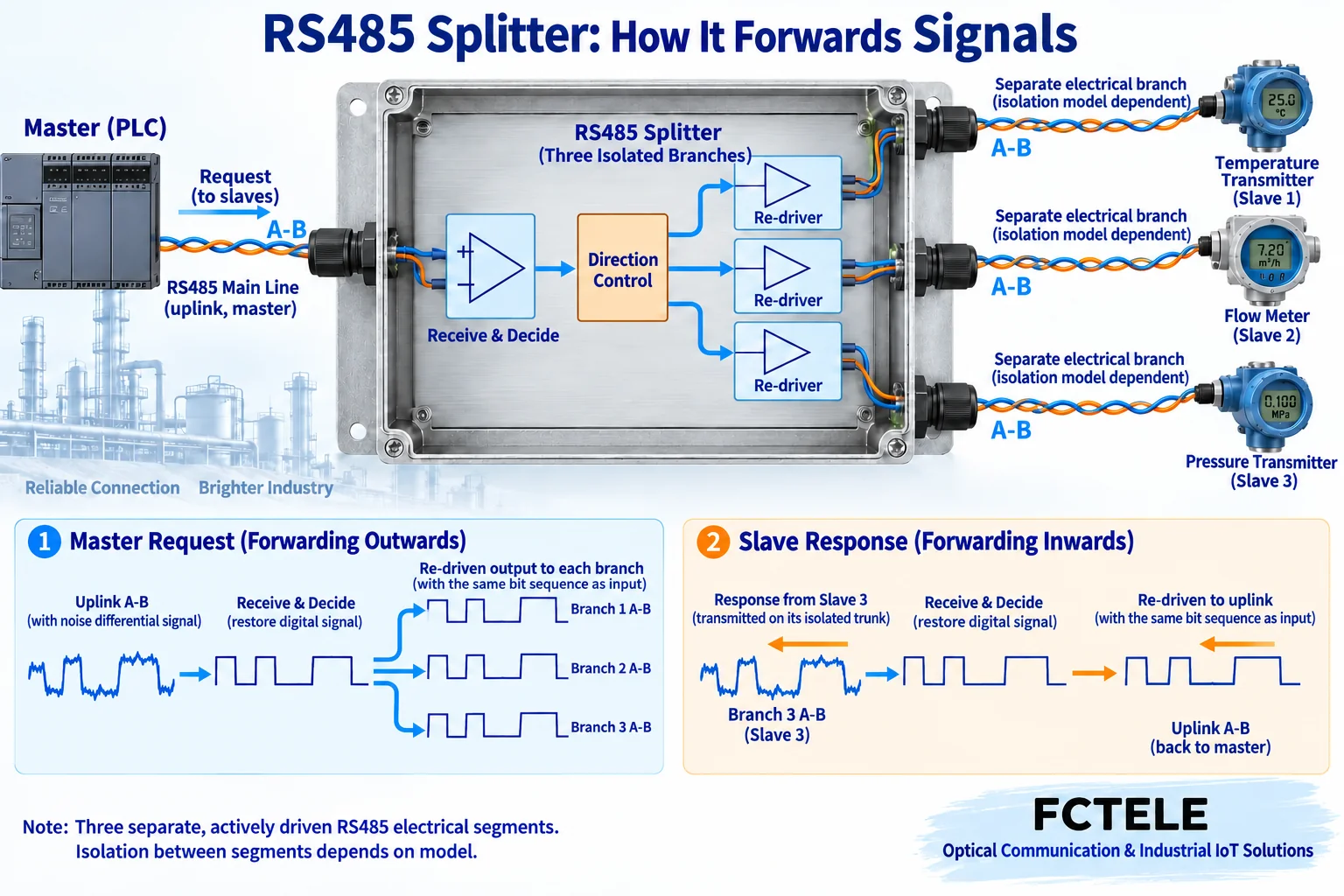
3. Active segmentation is different from passive star wiring
If you do not add active equipment and simply twist several long lines into a star, multiple forks and line ends will form. When the signal propagates to a place where impedance changes, it may reflect, and the voltage at the receiving position may ring or cross zero incorrectly. The problem is more obvious under faster edges and long-line conditions. Adding a hub with independent drivers means splitting these long directions into independent electrical segments, and then designing the wiring conditions for each segment separately.
The hub may appear as a star on the outside, but each downstream branch should still connect devices in bus fashion: the trunk passes continuously through the nodes, the node drop lines remain short, and you should not arbitrarily split one branch again into a long star. The output ports are not the same passive bus, so you cannot reconnect the A and B wires of two downstream ports together, and you should not use one return wire to connect different branches end-to-end into a loop. Whether cascading is allowed and how many levels are allowed must be based on the specific device manual.
4. Termination resistors are arranged at the two ends of each electrical segment
Termination resistors are connected across the wire pair to match the cable’s characteristic impedance and reduce reflections at the end. Common designs use a termination value that matches the cable impedance, but you should not install a resistor on every instrument just because you see “RS-485.” Too many terminations increase the driver load and may also pull down the differential voltage. For branches that require termination matching, you should identify the two physical ends of that segment and check the termination arrangement on the hub side and the far end separately.
Some products have built-in switchable termination or bias circuits. Bias is used to establish a stable idle decision condition when no one is transmitting, and its purpose is different from end matching; first check the device’s built-in situation, then arrange external components. When checking wiring with power off, you must also consider that the measurement result includes the internal network, and you cannot judge whether the installation is correct from only one resistance reading. Different manufacturers may have inconsistent A/B names and positive/negative definitions, so you should compare according to the terminal functions at both ends and the manual, not blindly connect by letters.
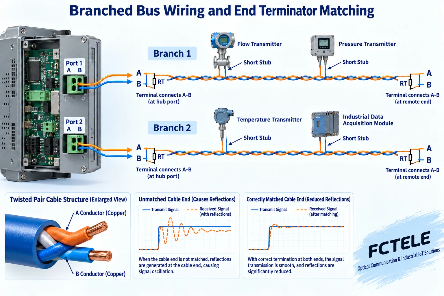
5. Isolation, segmentation, and surge protection each have their own role
Independent drivers can distribute the load to different network segments, while electrical isolation reduces direct conductive coupling between different areas. You need to confirm where isolation exists: is it only between the upstream and all downstream ports, or are the downstream ports also isolated from each other; after signal isolation, are power and field reference ground still shared. Only when independent isolated power and signal isolation work together can different field electrical domains be formed.
Feichang Technology FCC-D8J documentation lists eight channels, optional upstream interfaces, and an isolation structure, suitable for serial wiring that requires multi-direction segmentation; the FC-D8JM with per-channel short-circuit detection has additional fault identification and cut-off mechanisms. You cannot assume that the intelligent protection of the latter applies to any ordinary hub. Isolation withstand voltage is also not the working voltage that a communication port can accept, and surge ratings do not mean it can withstand mains misconnection or direct lightning strike.
6. Connect step by step according to a hypothetical project
Suppose a control cabinet needs to read instruments in two places, with two devices at each place. First use the master and one instrument in a short-line environment to confirm serial parameters, protocol functions, and address, then add one branch of the hub, keep the same set of parameters, and confirm the complete response and checksum. Then add instruments one by one, assign a network-wide unique slave address, and finally add the second branch. This order can separate line extension problems from software configuration problems.
Address uniqueness is for the protocol network visible to the same master, not for each branch restarting from address 1. A master request may be distributed to all branches. If two devices have the same address and respond at the same time, the return transmission will conflict. A multi-port device does not automatically increase the throughput of the master serial port; after the number of devices increases, the polling cycle also includes request transmission, slave processing, return message, direction switching, timeout, and retry.
7. Acceptance should look at messages and application results
After wiring is complete, record the model, power supply conditions, length of each segment, number of nodes, cable type, termination positions, and grounding scheme, then continuously check successful responses, checksum errors, timeouts, and application refresh cycles. Indicator lights can only show part of the transmit/receive status; a lit light does not mean the master has read the correct register. First obtain a stable baseline on a single branch, then gradually connect the remaining branches, and keep comparison records before and after expansion.
If frequent timeouts begin after adding a certain area, first isolate that area for comparison, then check address duplication, parameter inconsistency, end matching, polarity, and node power. For devices with fault isolation, you should also verify the action and recovery process under low-voltage test conditions permitted by the manufacturer; you must not arbitrarily create a short circuit on a running production bus. A hub solves part of line extension, but a reliable system still requires suitable protocol scheduling, wiring, and segment-by-segment acceptance.
Benefits and costs of repeater extension
The benefit of repeating or multi-channel segmentation is to re-drive the signal in each electrical segment, reduce the effect of potential differences across segments according to the model, and arrange scattered devices on more reasonable lines. It cannot restore data that has already been misjudged, nor does it automatically increase the master’s message processing capability. Multiple branches still share the upstream polling time. After connecting more devices, you need to recalculate the complete acquisition cycle including response, timeout, and retry.
The costs include additional power supply, direction switching and propagation delay, installation and maintenance points, and termination matching work. Ordinary transparent RS485 repeaters and HUB segments must use compatible serial formats; you cannot set different baud rates just because they are segmented. When serial services require matching dedicated buffering or protocol conversion devices, their configuration and timing should be checked separately. You cannot infer ordinary 485 HUB functions from CAN bus or Ethernet buffer descriptions.
Before use, first confirm whether you really need line extension, isolation, or multi-direction branching. RS485-to-RS422 conversion is valid only when the corresponding model explicitly supports it; you must separately check the two-wire half-duplex and four-wire transmit/receive terminals, and you cannot convert arbitrarily just because of the name “repeater.” Change only one network segment at a time, keep the original configuration, and then accept it based on real messages, error counts, and continuous operation results.
Sources:Feichang Technology RS485 hub product category;Feichang Technology FCC-D4JM four-channel product description;Feichang Technology FCC-D4M buffered multi-master product description;Feichang Technology FCC-D8J eight-channel specification;Feichang Technology FC-D8JM intelligent eight-channel product description;TI RS485 Design Guide;Modbus serial line specification entry. The diagrams explain general mechanisms; they are not actual PCB, product physical object, measured waveform, or certification document; model capabilities are subject to the corresponding documentation and delivered version.
Translated from the Chinese technical article. Source first published: 2023-11-07. Source last revised: 2026-10-13T12:28:34+08:00. Read the Chinese source
