


Layer numbers describe the processing object, not a direct speed comparison
Connecting terminals in the same workshop, connecting two IP subnets, and assigning new connections to different servers are three different tasks. Layer 2 switching mainly looks at MAC and VLAN, Layer 3 routing mainly looks at destination IP and routing information, and Layer 4 load balancing also uses transport layer information and corresponding path selection mechanisms. You should first determine which task needs to be completed; you cannot understand a higher layer number as a clearer picture, a faster network, or more complete security functions.
The layer numbers of the OSI model help describe the processing level, but product names may mix multiple functions. A Layer 3 switch can still perform Layer 2 forwarding and may also filter traffic by TCP or UDP port; this does not prove that it has server load balancing. So-called Layer 4 switching often refers to a specific traffic distribution capability, not necessarily a fourth-tier product after a simple upgrade of an ordinary switch.
Layer 2 learns MAC from the ingress and finds the egress
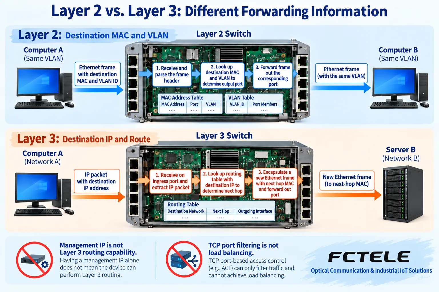
After a switch receives an Ethernet frame, it usually learns the relationship between the source MAC and the ingress, then looks up the destination MAC within the corresponding VLAN range and selects an allowed egress. Known destinations are forwarded directly; unknown unicast and broadcast are flooded according to applicable rules, and are usually not sent back out the original ingress. Flooding does not mean all VLANs receive the data; MAC table aging, filtering, and port status also affect the actual path.
Two terminals in the same subnet usually first obtain the peer link address through applicable neighbor discovery mechanisms such as ARP. A switch can have a management IP for administrators to open a page or obtain statistics, but the management IP is not the same as a terminal’s cross-subnet gateway. The MAC table answers which Layer 2 port a device is on; it cannot replace the routing table, and buffer capacity and MAC table capacity cannot be treated as the same resource.
Layer 3 redelivers packets according to the IP path
When the target is not on the local subnet, the terminal hands the packet to the corresponding gateway. At this point the IP destination is still the target terminal, while the destination MAC of this Ethernet frame is the gateway. The routing device checks the IP packet, selects the applicable route and next hop, and then rebuilds the frame header on the next Ethernet link. Ordinary IPv4 routing also involves TTL decrement and corresponding header checksum updates, so you cannot say the entire packet remains unchanged.
Hardware can efficiently process packets based on established forwarding information, but you should not interpret all architectures as routing the first packet and then only looking at MAC for subsequent packets. Different implementations use different table entries and processing paths, and packets must still satisfy Layer 3 forwarding and policy conditions. Forwarding information may come from directly connected, static configuration, or supported dynamic routing mechanisms; having Layer 3 capability does not mean supporting all routing protocols.
Layer 4 port filtering and load balancing have different purposes
TCP and UDP headers contain port fields used to identify transport endpoints. Devices can match ports and use this for ACL permits, traffic classification, or queue scheduling, but these operations mainly permit, deny, or arrange traffic and do not necessarily select a backend server. Port numbers alone also cannot prove that packet content belongs to a certain application; actual services can use different ports, and encryption and tunneling can also change visible information.
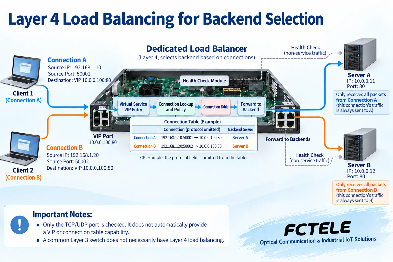
The goal of Layer 4 load balancing is to distribute connections or traffic to backends according to applicable rules. It usually requires a virtual service entry, backend members, selection policies, and corresponding connection or traffic state; whether health checks are performed, how affinity is maintained, and which forwarding method is used depends on the implementation. Checking Layer 4 fields, providing NAT, and having complete load balancing capability cannot be equated with one another.
How VIP and connection tables hide backends behind a service entry
In one common deployment, a client accesses a virtual service address VIP, and the load balancing device selects server A or B according to policy and saves the corresponding relationship for that connection. Subsequent packets belonging to the same connection are sent to the already selected backend according to applicable state, rather than randomly changing servers for every packet. In the figure, connection A to A and connection B to B are teaching examples; they do not mean all scheduling algorithms must distribute in turn.
Some modes rewrite the destination address or port, and responses also need to return to the appropriate processing path according to that mode; other modes use different forwarding designs. You cannot require all implementations to have exactly the same NAT actions. Connection tables, session persistence, and backend health checks are related but different tasks; after a backend failure, new connections can be transferred, but this does not guarantee that existing connections and application state recover without loss.
Choose resources by requirement; do not treat a checklist as a performance promise
Layer 2 requires checking ports, VLANs, MAC learning, and uplinks; Layer 3 also requires checking routing and neighbor resources, required policies, and applicable forwarding methods; load balancing focuses on virtual services, concurrent connections, new connection capability, backend management, and health checks. Each resource answers a different question. More table entries do not directly mean a single service is faster; when testing, you must specify traffic direction, frame length, protocol, and enabled functions.
When multiple gigabit ingress ports share one gigabit egress port, total traffic is still limited by the shared egress. Packets involving additional processing may enter the software path, and performance conclusions must correspond to the target function combination. When calculating switching capacity, also pay attention to the vendor’s basis for counting unidirectional or bidirectional traffic; you cannot assert that all policies can run at wire speed simply by multiplying port count by rate. Actual service response is also affected by terminals and applications.
The functions of industrial Layer 3 products cannot be expanded into Layer 4 products
The Feichang Technology 10-gigabit 4-fiber 8-copper Layer 3 managed switch page lists IP routing, Layer 3 ports, and ACLs, and can serve as a specific object for checking cross-subnet aggregation and access rules. Its optical and electrical interfaces are suitable for corresponding line connections, and management functions help confirm paths and maintenance. Before use, you still need to check firmware, resources, configuration, and service conditions; you cannot claim that all tasks have deterministic latency based on the word industrial.
The above page does not have enough corresponding explanation to prove complete VIP server load balancing, so this article does not promote it as a Layer 4 load balancing device. If a project needs to distribute services to multiple backends, you should choose another product or software solution that clearly provides the corresponding function, and check the forwarding mode, application state, and maintenance method. Network layer routing redundancy also cannot directly replace application service state synchronization.
Use the actual communication path to complete selection and troubleshooting
When a small production line only needs same-VLAN connections, first confirm Layer 2 forwarding is sufficient; when multiple service subnets need to communicate with each other, then plan gateways, routing, and access permissions; only when multiple servers need to handle the same service entry should you further evaluate load balancing. These functions can be deployed at different locations in the same network, and one device is not required to take on all roles. First draw the path clearly, then compare corresponding products.
For acceptance, first verify physical connections and same-domain communication, then check cross-domain addresses, gateways, and return routes, and finally check virtual services, connection state, and backend health as needed. Verify both successful services and access that must be denied, as well as allowed fault changes. Save model, version, and configuration; do not treat one large file transfer working normally as proof that routing, isolation, and server failure recovery are all qualified.
Data note: The principle diagrams have been checked against technical content and are used to explain general mechanisms; they are not product photos or measured records. Specific interfaces, modes, and capabilities are subject to the selected model, version, and on-site verification.
Verification materials:RFC1812: Requirements for IPv4 Routers
RFC3022: Address Translation and Connection Mapping
F5: Layer 4 load balancing mechanisms
Feichang Technology 10-gigabit 4-fiber 8-copper Layer 3 managed switch
Related technical topics:How to network industrial Layer 3 switches: VLAN gateways, access policies, and service acceptanceHow to choose between Layer 2 and Layer 3 switches: forwarding principles and performance boundaries
Translated from the Chinese technical article. Source first published: 2019-11-27. Source last revised: 2026-10-13T11:37:04+08:00. Read the Chinese source
