


Start with the conclusion
Confirm three things before wiring
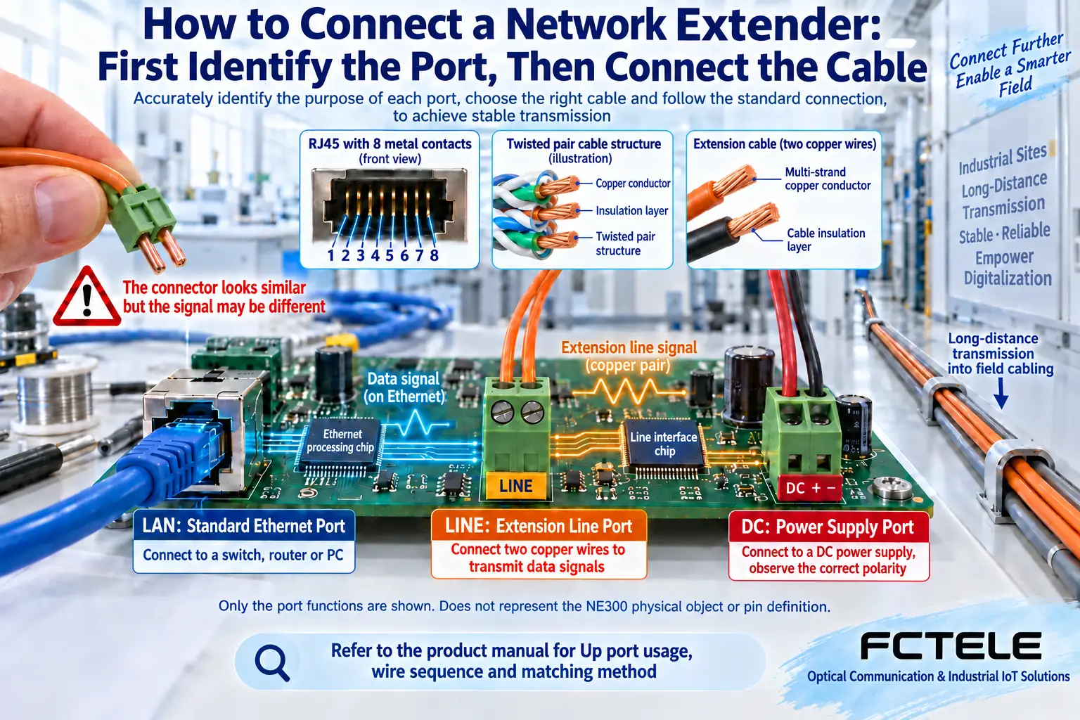
When wiring a network extender, first identify the ordinary Ethernet side, the extension line side, and the power side. The ordinary Ethernet side connects to a switch or terminal; the extension line side connects to a matching far-end device or a specified device; the power side is powered according to the nameplate and manual. A port name like Up usually suggests an uplink role, but you cannot judge from the name alone whether it is an ordinary Ethernet port, a dedicated long-line port, or a powered interface.
This article is suitable for first-time installation and for checking an existing line that is unstable. First obtain the manual that corresponds to the actual model and hardware version, then check the wire sequence, pairing mode, distance conditions, and power. Acceptance should be divided into a short-line baseline, the original line connection, and an actual service test; do not jump from a lit LED straight to delivery, and do not plug an unknown line into any RJ45 port.
How to use NE300 information without choosing the wrong model
The existing official website introduction for the NE300 model involves Up and the connection status of downlinks 1, 2, 3, and 4, and also involves 10M mode, specific cables, and cascading conditions. These are clues for identifying materials and asking the supplier, and cannot replace the complete installation manual for the corresponding version. At present, its port pins, pairing topology, remote power supply, or cascading performance table have not been verified from the product details, so a construction drawing cannot be made directly based on this.
Before installation, take clear photos of the front and back of the device, the nameplate, the port markings, and the power adapter, and confirm with the supplier the electrical interface of the Up port, the downlink port rate, how many devices are needed, and the requirements for each line segment. Models with the same name from different manufacturers may also differ. Do not infer distance from the numbers in the name, and even more importantly, do not treat the numbers for a single segment, different rates, and multiple devices in series as the same working condition.
Why you cannot guess ordinary Ethernet ports and extension ports by appearance
LAN is a common marking for a local area network access port. LINE, DSL, or a manufacturer-specified Up port may correspond to the line side, but the manual definition is final. RJ45 is a common connection form, and ports with the same appearance can carry different electrical signals. Connecting a dedicated line port to an ordinary switch may result in no connection at all; if the port carries power, misconnection may also damage equipment.
In a VDSL2 solution, the line signal passes through a copper pair, and the modems at both ends handle conversion. You cannot directly connect ordinary Ethernet ports with just two wires. Ordinary twisted-pair long-distance mode, coaxial mode, and fiber mode each require the corresponding medium and interface. The wire sequence, whether polarity is required, and whether existing services may share the line should all be checked item by item; do not copy the wiring photo of another model.
First use a short line to establish a normal baseline
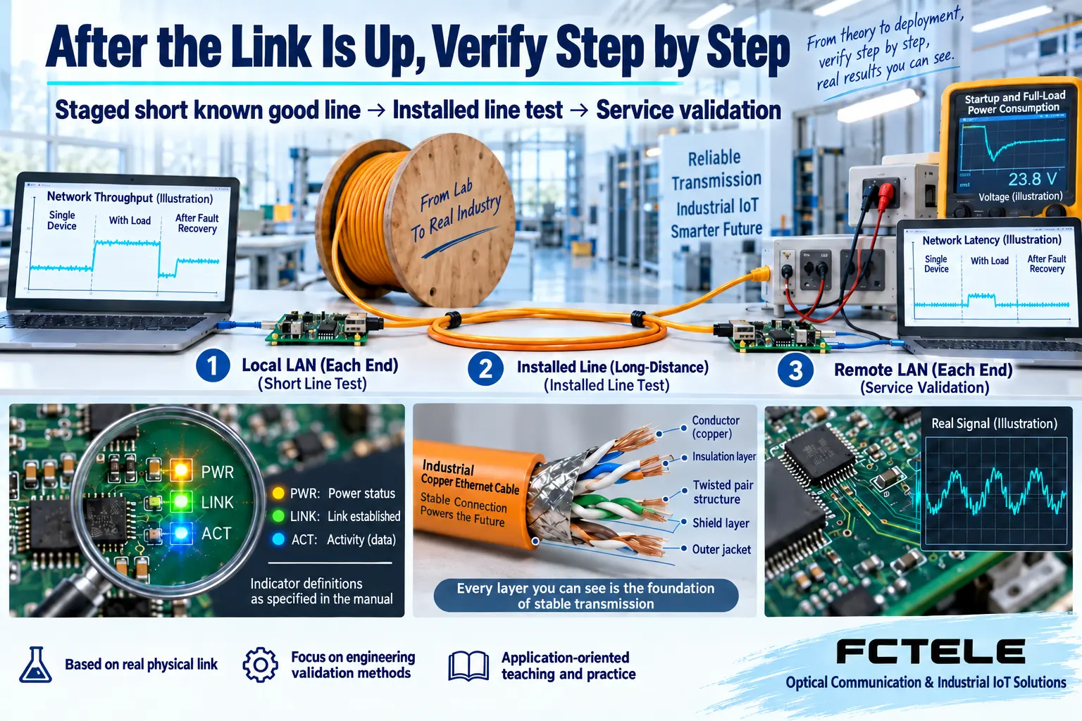
On the workbench, confirm the power supply range, polarity, and power capability at both ends; if the manual requires CO and CPE roles, set one end as the center side and the other end as the user side. Use a confirmed normal and compliant short line to connect the far end, then connect ordinary LAN test equipment. Getting the short line working first helps distinguish device or configuration problems from on-site long-line problems.
Record the model, hardware and firmware version, DIP switch or configuration, port connection position, and indicator light changes at both ends. If the short line still does not work, first check the pairing mode, line port, and Ethernet port negotiation, and avoid directly connecting the on-site long line, multiple terminals, and an old power supply all at once. Change only one condition at a time so you can know which step caused the state to change.
What the Power, Link, Act, and Up lights can each prove
Power usually indicates power status, Link usually indicates that the corresponding physical link is established, and Act usually indicates that data activity exists; the actual light color, flashing, and multiplexed definitions follow the model manual. A lit power light cannot prove that the full-load voltage is stable, a lit link light cannot prove that there is enough throughput, and a flashing activity light cannot prove that the required service is successful, because broadcast or retries can also cause activity.
When checking NE300-related equipment, first check power according to the confirmed materials, then check the Up connection status, and finally check the downlink ports one by one. If one downlink port is not lit, swap in a known-good short Ethernet cable and cross-check with the terminal; if multiple ports are abnormal, compare the common uplink, power, and configuration. Indicator lights only help narrow the scope and cannot replace service testing and error statistics.
Check segment by segment when connecting to the original line
Before changing to a long line, confirm the line purpose, length, conductor material, wire diameter, intermediate joints, and whether it is live. It is forbidden to directly connect unknown carrier telephone lines, alarm lines, or power lines to the equipment. Line measurement follows on-site safety procedures; damp joints, oxidation, looseness, too many branches, and running parallel with strong interference cables should all be recorded as separate investigation items.
If the short line works but the long line does not, first compare the line and matching conditions; if both ends are connected but the service does not work, then check the terminal IP, VLAN, and gateway. IP handles network addresses, and VLAN separates different logical networks. A normal physical link at both ends does not mean the logical networks must be consistent. Troubleshoot physical problems first, then address and service problems, and avoid changing all configurations at once.
How to check power, cascading, and multi-terminal access
For a long-line solution, also confirm whether the far end is powered by a local power supply or draws power from the line, and whether the terminal needs an additional power supply. Measurement should cover the far-end state during startup and concurrent services, and you cannot look only at the adapter output at no load. Standard PoE power and dedicated line power cannot be mixed; the power range, protection, and grounding should be implemented according to the model and project design.
When multiple downlink ports share an uplink, the total service is limited by the shared uplink capacity. Teaching example: four devices each need 4 Mb/s, and the uplink service has already reached 16 Mb/s; if the actual long-line mode is only 10 Mb/s, adding downlink ports cannot accommodate this traffic. Cascading also adds power points and forwarding stages, so it should be checked segment by segment; do not assume that arbitrary series connection is allowed just because two enclosures look the same.
Leave a wiring record that can be reviewed before delivery
Complete a bidirectional capacity test on the target line, then connect the actual terminals and observe continuous service: for cameras, watch recording and bitrate fluctuations; for control devices, watch requests, responses, and timeouts. Record port numbers, cable labels, negotiation status, errors, and reconnections, and verify recovery after power loss and disconnection according to the project agreement. The acceptance standard comes from the service requirements, not from the color of a particular indicator light.
If the site has fiber optic cable conditions, you can compare the Ethernet electrical port and optical interface solutions of Feichang Technology B-series fiber optic transceivers; this is another medium choice and must match the optical interface and power at both ends. When you need an explanation of principles, read the basic article on network extenders; when you need a budget comparison, read the selection article, and complete wiring confirmation, capacity confirmation, and cost confirmation separately.
Material note: The principle diagrams have been checked against technical content and are used to explain general mechanisms; they are not product photos or measured records. Specific interfaces, modes, and capabilities are subject to the selected model, version, and on-site verification.
Verification materials:PLANET: VDSL2 pairing, line, and performance conditions
TI: Cable and signal conditions for long-distance single-pair Ethernet
Feichang Technology: Fiber optic transceiver product categories
Feichang Technology: B-series 2-port 100M fiber optic transceiver
Translated from the Chinese technical article. Source first published: 2022-01-21. Source last revised: 2026-10-13T11:40:22+08:00. Read the Chinese source
