


Start with the conclusion
Understand the conclusion first: what is extended is the connection; what changes is the line transmission method
A network extender is used to connect two Ethernet access points that are far apart. It is not a connector that can lengthen a network cable indefinitely: some devices convert frame data into a signal suitable for long copper lines and restore it at the other end; some receive and send the signal again in the middle; fiber solutions convert electrical signals into optical signals. Different media and internal technologies mean different wiring methods, distances, and capacities.
This type of device is suitable for renovating existing cabling, connecting scattered surveillance points, and connecting remote control equipment. First confirm what cable is available on site, then confirm how much capacity the service needs and how the remote end will be powered. The key acceptance points are the actual bidirectional throughput on the target line, errors and reconnections, concurrent services, and fault recovery; a link light or one successful Ping cannot replace these tests.
Why ordinary network cables cannot be lengthened indefinitely
Ordinary twisted-pair Ethernet has corresponding link length conditions. Common 100 Mbps and 1 Gbps copper cable channels are usually designed for no more than 100 meters. This number corresponds to specified cable and connection conditions, not a common physical upper limit for all Ethernet technologies. Electrical signals attenuate through copper cables, connectors and impedance changes can also cause reflections, and interference from nearby lines increases the difficulty for the receiver to judge data.
The receiving process can be understood as hearing a sentence clearly in a noisy environment, but the electronic receiver also has to judge level, timing, and encoding. Simply amplifying may also amplify noise and cannot recover information that can no longer be distinguished. An active device in the middle needs to correctly receive, process, and then send; long-line devices at both ends need to match the line technology; both require corresponding operating conditions.
Copper modulation type: how the two ends send frame data across
Taking the VDSL2 type as an example, frame data received by an ordinary Ethernet port is sent through a copper pair after internal bridging and modulation processing. Modulation means changing certain characteristics of the electrical signal according to the data; the far end demodulates and decodes it, then hands it to the receiving device through an ordinary Ethernet port. Changing the bearer method does not mean the device automatically converts Modbus, video, or other service protocols into another protocol.
The two ends also need to establish a line connection and use compatible configurations. Some VDSL2 products require one end to be set as CO and the other as CPE, that is, the central-side and user-side roles. This rule comes from the specific technology and cannot be generalized to mean that all network extenders require the same switch; nor can you assume that two devices will necessarily interoperate just because both are called LRE.
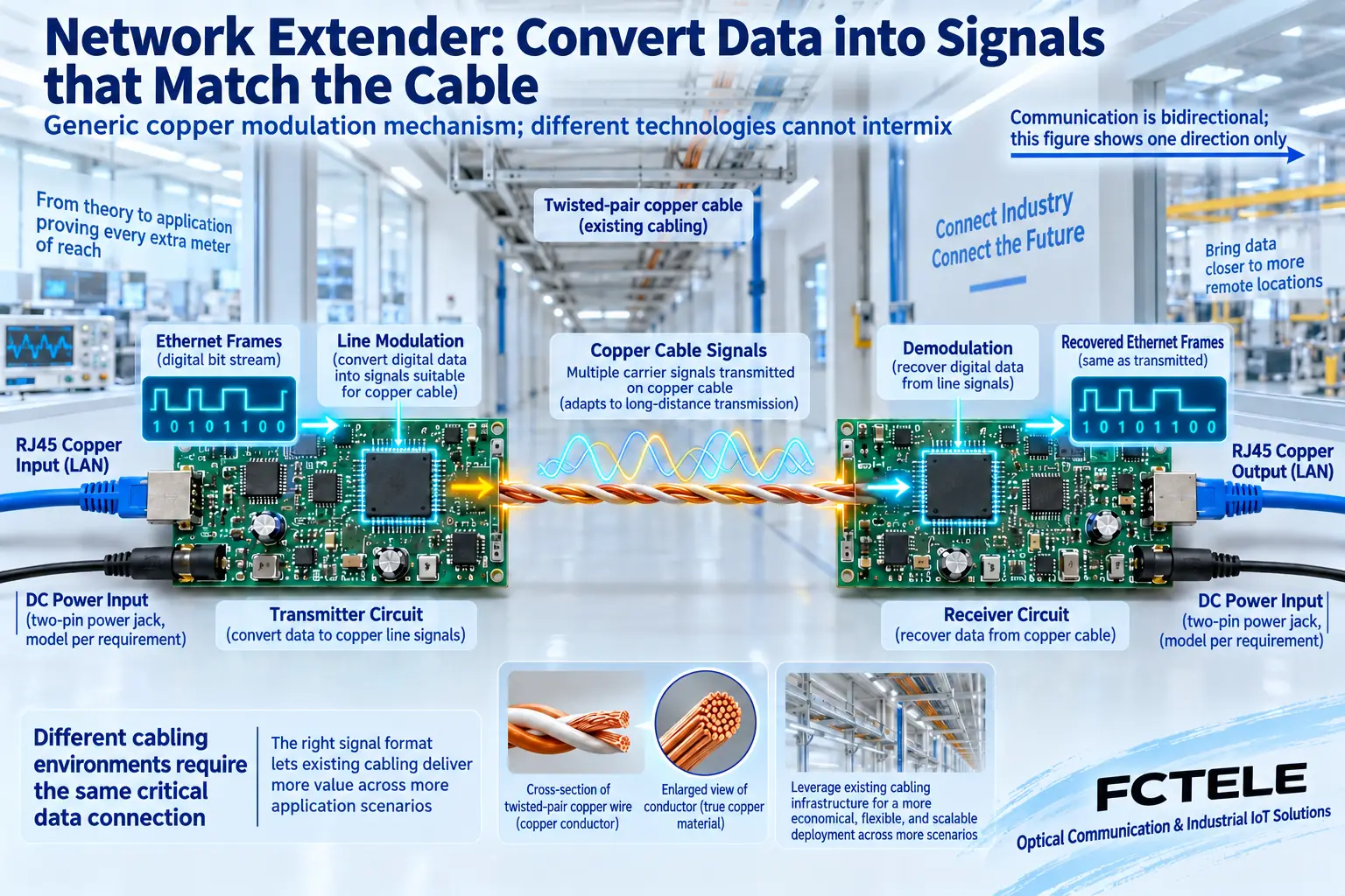
How to distinguish telephone line, twisted pair, coax, and fiber
The telephone line type usually uses qualified copper pairs; the coax type uses a coaxial line formed by a center conductor, insulation layer, and outer conductor. They must match the line port and signal technology. The connector shape only shows how to plug in; it cannot prove that the signals are the same, let alone guarantee that telephones, analog video, or other services on existing lines can be shared without processing.
Ordinary network cable type long-distance ports may use a dedicated mode or limit the rate; fiber links must match fiber type, module, wavelength, and optical power budget. 10BASE-T1L is also an independent Single Pair Ethernet physical layer standard, using one pair of wires to carry 10 Mb/s full-duplex communication. It is different from ordinary RJ45 Gigabit networks and cannot be directly mixed with VDSL2 line ports.
Distance, port rate, and actual capacity are three separate questions
A device having a 100 Mbps access port only shows that the port supports the corresponding rate; it does not prove that the long line in the middle always provides 100 Mbps service capacity. Modulated devices may negotiate capacity as line loss, noise, and configuration change; fixed-rate technologies may increase errors or even drop the link after conditions worsen. Do not draw all technologies as one curve where speed continuously decreases as distance increases.
Manufacturer performance tables should be read together with distance, wire gauge, operating mode, direction, and test method. Upload and download may be asymmetric, and camera return traffic should especially be tested in the direction from the site to the center. Suppose four video streams each need 4 Mb/s; the total service is already 16 Mb/s, and transmission overhead, bitrate fluctuations, and other communication must also be counted. This is a planning example, not a promise for any model.
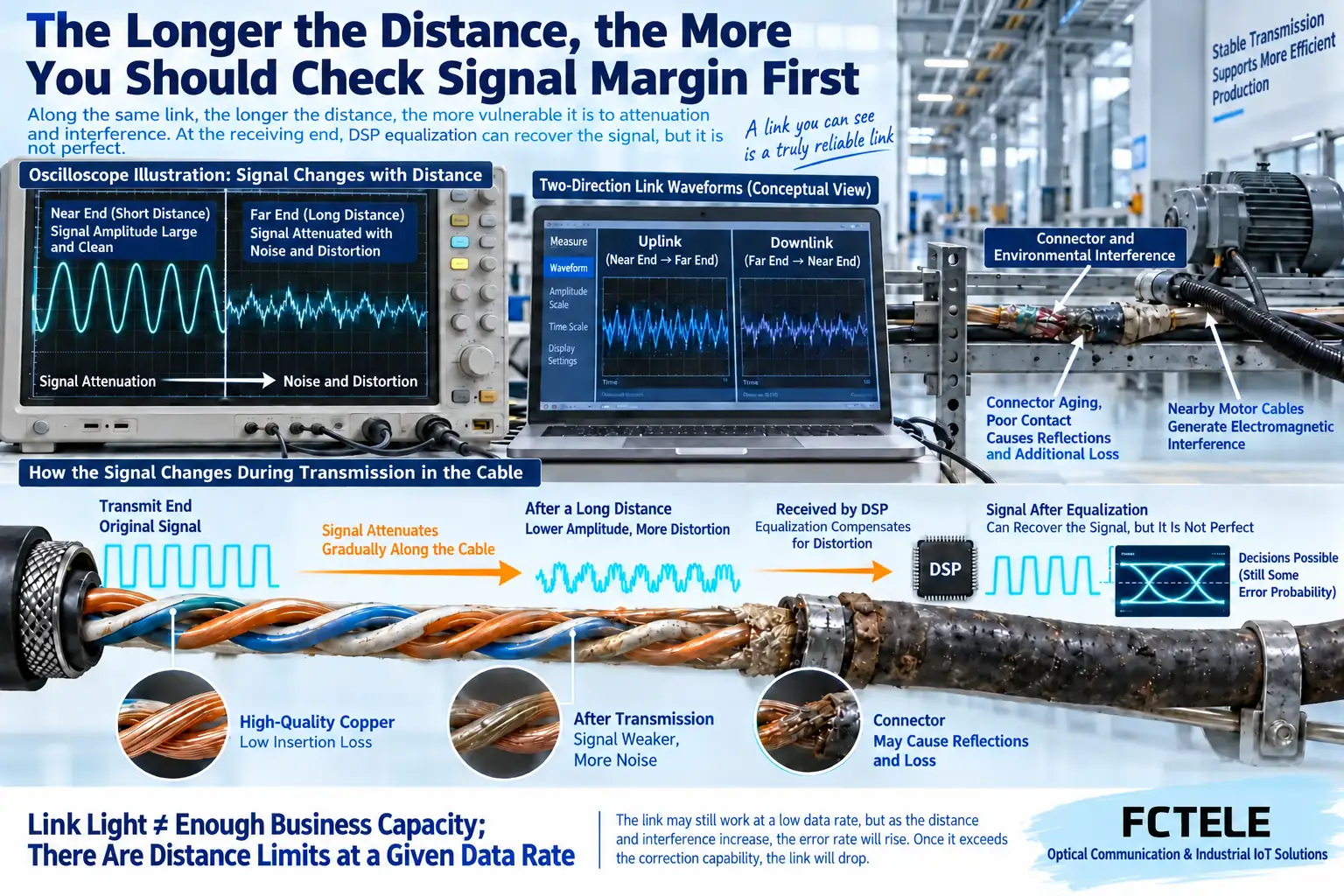
Why power and cascading must be checked separately
The remote extender itself needs power, and the terminal also needs power. Remote power over the line and providing standard PoE at the terminal Ethernet port are different capabilities; seeing remote power does not mean the camera can also draw power. Copper has resistance, and current passing through it causes voltage drop and power loss. Problems may appear at startup or full load that were not found in standby testing.
Cascading requires every segment to meet signal, capacity, and power conditions. Stringing two devices together cannot simply add the advertised distances; the power consumption, forwarding capability, latency, and fault points of the intermediate device also increase. For unknown lines, first confirm the purpose and electrical state, and follow site procedures when checking with power off. Do not connect operating telephone lines or live wire pairs directly to extender ports to try your luck.
When is it more appropriate to switch to fiber
When usable copper cable already exists, construction is restricted, and service capacity is not high, the corresponding copper solution can be evaluated. When laying fiber cable is allowed, connecting across buildings is needed, or capacity is to be expanded, fiber media converters and switch optical port solutions can be compared. Fiber media do not conduct current like copper, but endpoints still need power, and metal components in the fiber cable, lightning protection, and grounding still need to be handled according to the design.
Feichang Technology ordinary fiber media converter categories provide product directions such as 100 Mbps and Gigabit, among which the B series 2-port 100 Mbps fiber media converter performs media conversion through Ethernet electrical ports and optical interfaces, and can serve as a comparison object for fiber cable renovation. Specific power, optical interface, and distance configurations should be checked in the corresponding specifications. A fiber media converter is not a telephone line modulator, and an optical port cannot be directly connected to copper cable.
Complete acceptance with a repeatable record
First use a confirmed normal short cable for a paired link test, record the model, version, role, interfaces, and power, then switch to the target line. Record cable length, wire gauge, connectors, and sharing conditions, test upload, download, and simultaneous communication separately, and keep records of negotiated status, errors, and link drops during testing. Capacity, packet loss, latency, and continuous operating time should be determined according to the service agreement, and a uniform pass value should not be applied arbitrarily.
After connecting the actual video or control load, cover representative conditions such as concurrent peaks, device startup, and nearby motor start/stop; then verify recovery after power failure and cable disconnection, confirming that recording, control, and management connections can all recover. When instability occurs, locate it segment by segment according to the local Ethernet port, long line, remote Ethernet port, and power supply, rather than repeatedly restarting until it occasionally works.
Data note: The principle diagrams have been checked against technical content and are used to explain general mechanisms. They are not product photos or measured records. Specific interfaces, modes, and capabilities are subject to the selected model, version, and on-site verification.
Verification materials:PLANET: VDSL2 pairing, line, and performance conditions
TI: Cable and signal conditions for long-distance Single Pair Ethernet
Feichang Technology: Fiber media converter product categories
Feichang Technology: B series 2-port 100 Mbps fiber media converter
Translated from the Chinese technical article. Source first published: 2022-01-21. Source last revised: 2026-10-13T11:40:22+08:00. Read the Chinese source
