


MINI first describes the form factor, not a new protocol
MINI or pocket-sized usually means the device is small, but no single name can guarantee the dimensions, power consumption, and interfaces of all products. A small Ethernet fiber media converter still has to handle signal conversion between copper cable and fiber. Just because the enclosure is smaller, it does not automatically have PoE, network management, redundant power, or link fault pass-through, and it is not a new-generation standard that ordinary products necessarily evolve into from PoE.
The value of small devices usually shows up in cramped boxes, scattered sites, and easy installation, but the premise is that the interfaces, power supply, and environment meet the project. First confirm that what needs to be transmitted is Ethernet, and do not mix serial port, USB extender, or carrier PON terminal into the same category. The MINI in the name cannot replace the complete model number and technical parameters, and similar appearance does not prove that function or reliability is the same.
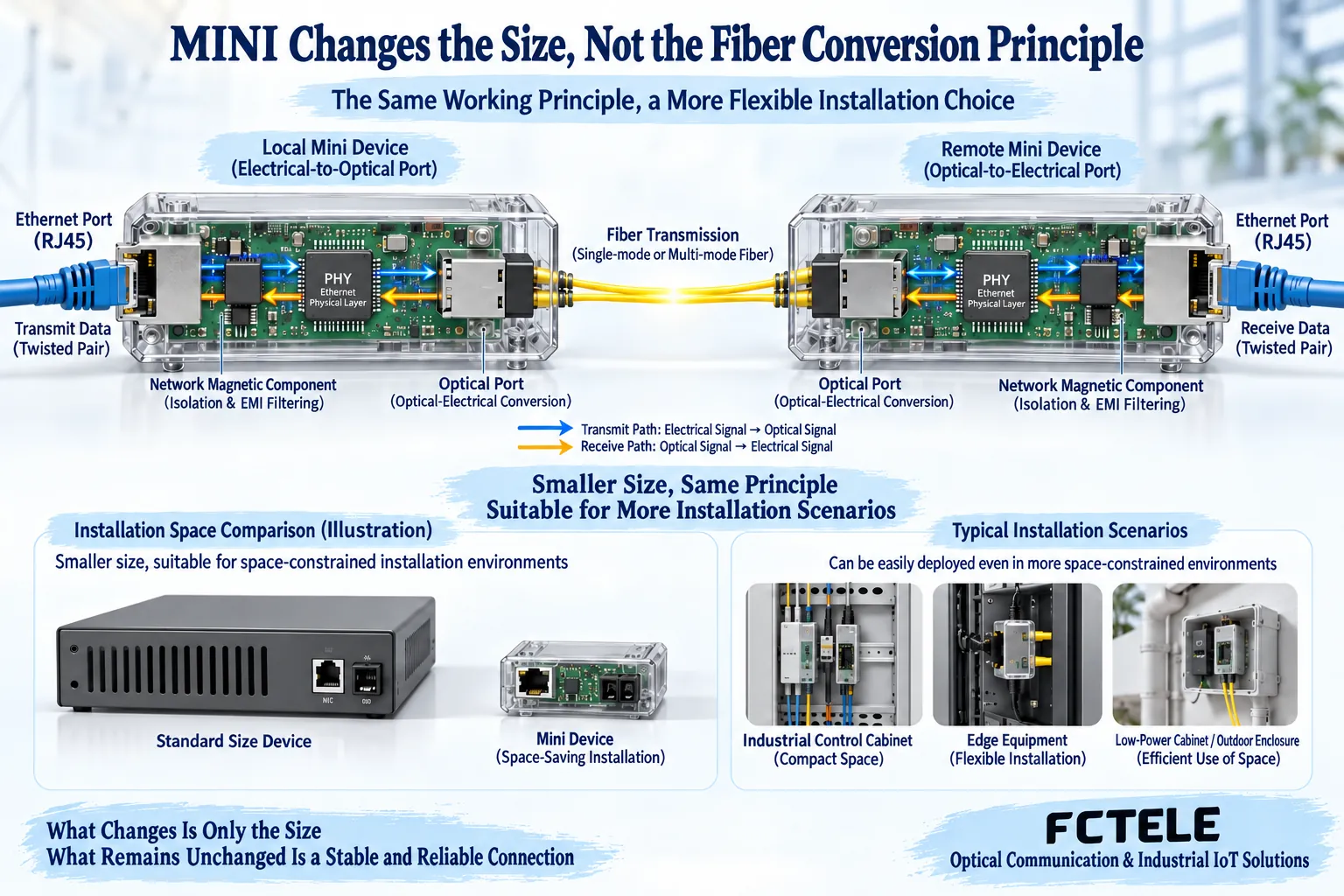
Inside, there are still two paths: transmit and receive
After copper cable connects to the RJ45 electrical port, the corresponding physical layer circuit handles line coding and hands the data to the optical-side transmit circuit; at the other end, the optical receive circuit turns the signal back into electrical information, which is then delivered from the electrical port. Some implementations include frame processing and buffering, while others focus on physical layer conversion; whether rate conversion is supported should be confirmed for the complete unit. A small package changes the layout but does not exempt these circuits from their operating conditions.
Dual-fiber requires local TX to connect to remote RX, with the two directions using different fiber cores. Single-fiber bidirectional usually uses complementary transmit and receive wavelengths to communicate over one core, and both ends can transmit and receive; MINI cannot be interpreted as necessarily using only one fiber core. Connector type and single-mode/multimode are different conditions, and being able to plug in the connector does not prove that wavelength, power, or Ethernet rate match.
Installation space must include connectors and cables
When purchasing, do not measure only the enclosure; also consider the power plug, RJ45 plug, optical connector, cable bending space, and access for maintenance tools. After installation, if the fiber cable can only be bent sharply, or the network cable plug presses tightly against the box door, the saved device volume may be exchanged for mechanical stress and difficulty with later maintenance. Allowable bending radius and tensile force should be checked in the actual cable data, not replaced by one universal millimeter number.
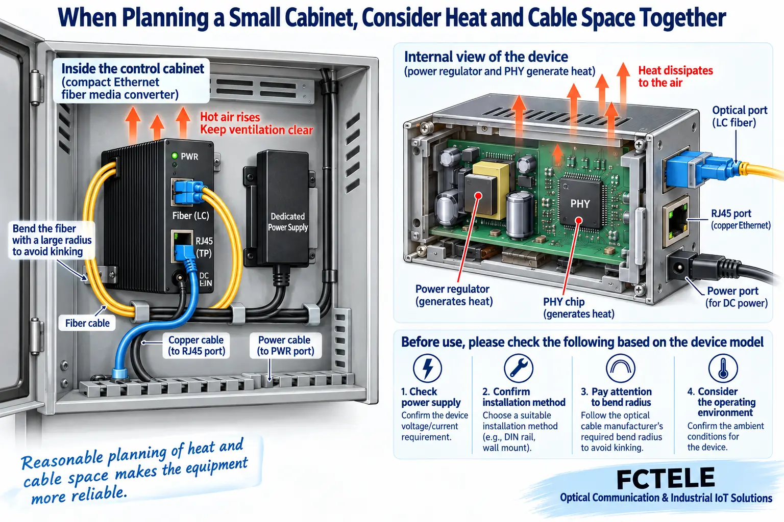
The mounting method must also be clear. Being able to place it on a desktop does not mean it has a DIN rail clip; having ears does not mean it is compatible with all rack trays; and a standalone box does not automatically become a plug-in card device. On site, fix it according to the product requirements, preserve ventilation and cable slack, and make port labels, status lights, and power supply identifiable. Avoid letting the device hang by cables, or blocking all heat dissipation space just to fit it into a small box.
Small size does not mean no heat
Power conversion, PHY, and optical components generate heat during operation, and the heat needs to pass through the circuit board, enclosure, and air to escape. When multiple devices are close together in a small box, the ambient temperature rises, or ventilation is blocked, the internal temperature rise may affect stability. A metal enclosure helps some heat dissipation paths, but it does not prove that the device has no heat, nor can you determine component operating temperature only by whether the enclosure feels cool or warm to the touch.
First check the complete unit power consumption, specified environment, installation heat dissipation, and power supply range, and observe continuous operation under the actual configuration. The allowable temperature in chip data does not equal the temperature at which the complete unit can operate under the same conditions; enclosure protection and waterproof capability also require separate evidence. Outdoor projects involve enclosures, condensation, dust protection, and power disturbances, so the device cannot be placed directly in an uncovered environment just because it is compact.
Power supply and PoE roles must be confirmed separately
External adapters, built-in power supplies, and other specified power interfaces are different solutions. Being able to insert the power plug does not mean voltage, polarity, load, and protection match; unknown adapters should not be swapped in at will. If the product description supports dual input, also confirm the redundancy mechanism, single-path capacity, and common power source. Two lines connected to the same failed source cannot form complete power backup.
PoE means the power sourcing or powered device capability of the corresponding copper port, not power transmission over fiber. A remote MINI converter still needs a power supply that meets the design, and whether the network terminal is powered by it must be checked by clarifying the role and power budget. A USB appearance also cannot be treated as a universal input specification; check it against the manual. Do not extend chassis dual-power or hot-swap features to every pocket-sized box device.
Find products from company materials, not parameters inferred from old articles
Feichang Technology’s ordinary type classification and B-series one-fiber one-Ethernet gigabit entries provide product entry points with corresponding interfaces and power forms, which can be used to compare site power and optical path configurations. The AC plus DC backup description of the built-in power version cannot be applied to the external adapter version. This time, no single size, power consumption, or temperature followed by all MINI devices was confirmed from these materials, so this article does not invent a unified specification for pocket-sized devices.
If a small body is needed, list the allowable space, mounting method, rates at both ends, fiber resources, power supply, and environmental conditions for the supplier, and let them confirm the specific deliverable model. A pluggable module solution also requires checking host support and module power consumption; a fixed optical port solution requires confirming the complete transmit and receive pairing. LFP, remote network management, and alarms are separate functions and cannot be considered satisfied just because the device is labeled smart or industrial.
Turn convenience into a reproducible acceptance check
First establish a baseline with a matched and power-safe short link, confirm the electrical ports, optical ports, and normal service at both ends, then run the agreed load in the official cable and installation box. Observe data, errors, and link changes in both directions, as well as the in-box environment and power status. The test duration and judgment basis should be stated according to project requirements; a single Ping or a lit light cannot prove long-term reliability.
Maintenance verification includes being able to identify the device and ports, conveniently disconnect the specified connections, replace adapters without pulling the fiber, and retest the service after recovery. If fiber break or power loss simulation is needed, perform it within the allowed window and record the recovery behavior; do not treat one model’s indicator light position as a rule for the entire category. The final selection conclusion is that a certain small device is suitable under these space, interface, and environmental conditions, not that MINI is naturally better than all ordinary devices.
Sources: TI PHY mechanism material ; Feichang Technology ordinary type classification ;B-series power and optical port configuration. Related: classification , complete selection . The images are generic mechanism illustrations, not actual models, PCBs, measured data, or customer cases; product capabilities are confirmed according to delivery materials.
Translated from the Chinese technical article. Source first published: 2019-10-24. Source last revised: 2026-10-13T11:10:04+08:00. Read the Chinese source
