


Converter classification is not a single-choice question. One device can be Gigabit, single-mode, single-fiber, standalone and unmanaged simultaneously. These describe different conditions. Identify service and endpoint interfaces first, then fiber, wavelengths, power and mounting. Industrial or long-distance labels alone cannot establish suitability.
1. Distinguish complete converters from modules
This article concerns complete Ethernet copper/fiber converters. Copper circuits recognize line signals, internal circuits adapt them and the transmitter converts electrical information to light. Reception reverses this to copper output. The service remains supported Ethernet; fiber does not automatically add dedicated video, telephone or serial protocols.
SFP is a pluggable module form factor normally installed in a switch or converter. It is not a complete powered RJ45 converter. Fixed-optics units supply optics with the host; pluggable units require separate selection of host and supported modules. Fitting mechanically cannot prove rate, protocol or host compatibility.
2. Rate classification: check both interfaces
Fast Ethernet and Gigabit identify nominal rates. Verify copper rates, optical Ethernet interface and permitted combinations separately. Copper autonegotiation selects a mutually supported mode; it does not make optics adapt to arbitrary speeds or guarantee Gigabit-to-Fast-Ethernet conversion.
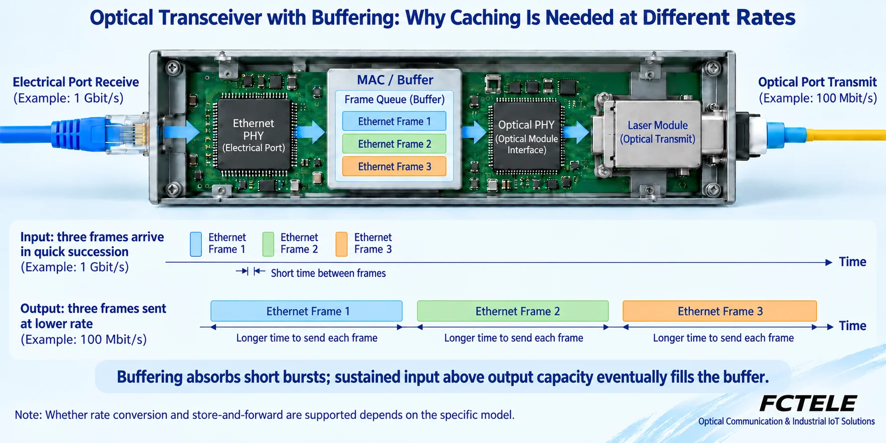
The PHY handles physical signaling and coding. Some conversion architectures emphasize same-rate physical conversion; others process frames with buffers and support specified rate combinations. Fixed Gigabit or adaptive wording cannot establish architecture, and one chip mode cannot define every FCTEL product.
An Ethernet frame is formatted data. Store-and-forward equipment receives it, performs supported checks and forwards it. Temporarily faster input enters a finite queue. Equal-length frames take longer at Fast Ethernet than Gigabit. Buffers absorb bursts but cannot eliminate sustained excess input. Full-buffer behavior depends on flow control and implementation; buffering is not a zero-loss guarantee.
3. Fiber mode and fiber count are separate classifications
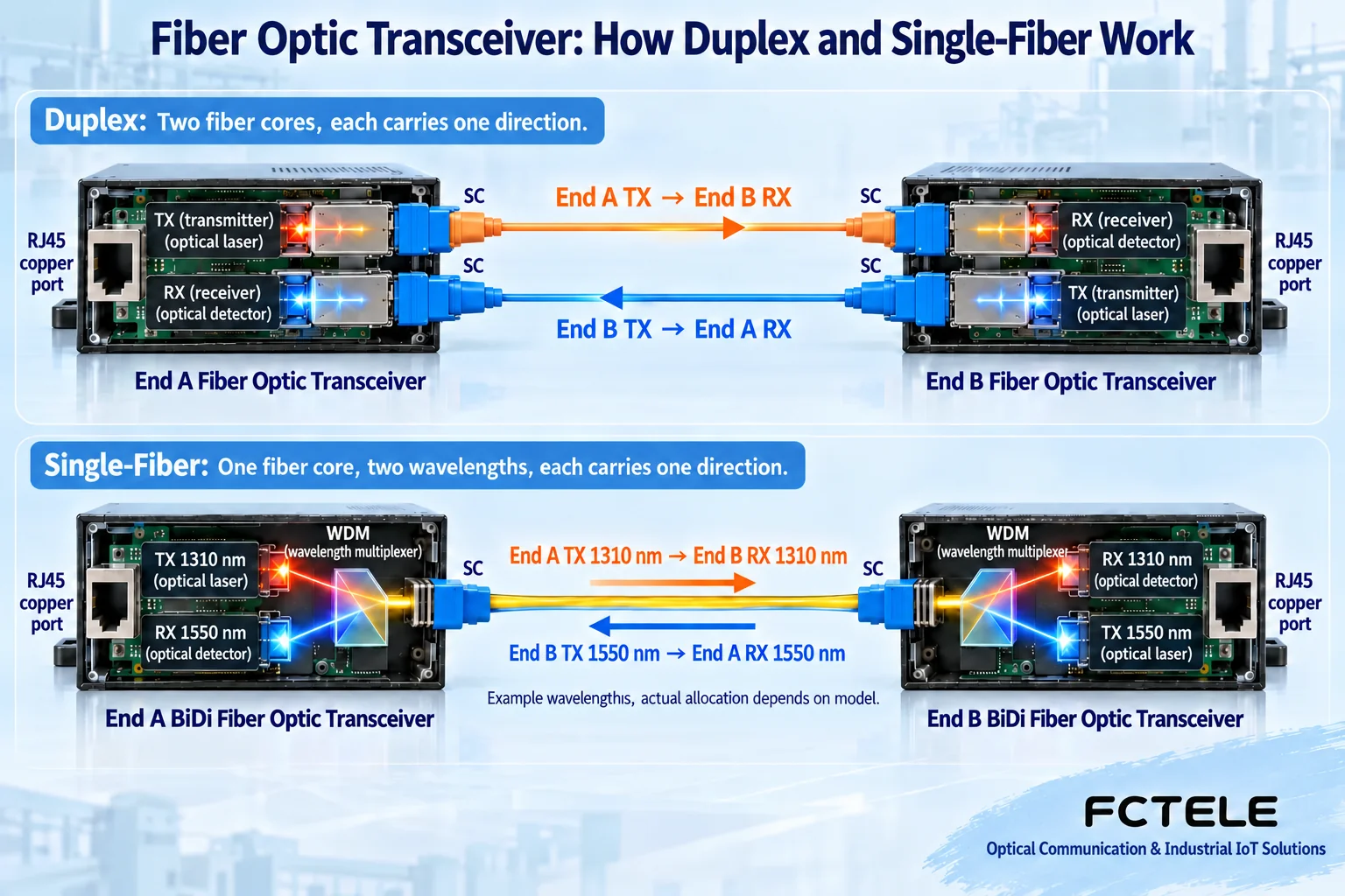
Single-/multimode describe propagation and optical conditions. Single-/dual-fiber describe physical core count. Single-mode does not mean single-fiber, and multimode does not mean duplex. Check cable identification, fiber documentation and optics rather than jumper color alone. Reach depends on standard, fiber grade, wavelength, power and loss; no universal multimode distance applies.
Duplex normally uses one core each way, with local TX connected to remote RX. Single-fiber BiDi commonly separates directions by wavelength: A transmission must match B reception and vice versa. Both ends transmit and receive, not one direction per box.
SC and LC describe connector mechanics, not speed or distance. Adapter jumpers do not alter wavelength, receive range or Ethernet type. Even with matching fiber/connectors, budget each direction to keep power above required sensitivity and below maximum input. Short distances do not make every module safe to connect directly.
4. Standalone versus chassis cards changes deployment and fault scope
Standalone units suit dispersed locations; cards centralize links. These choices concern space, power and maintenance organization, not a different optical protocol. Plan labels, cooling, slots, supply capacity and spares. A chassis can create a shared power failure point across services.
Central power does not guarantee central management or redundant supplies. Check hot-swap permissions, supported backplanes and management modules in complete system documentation. An external adapter does not restrict a unit to consumer use, and internal power cannot prove carrier-grade performance. Verify input range, isolation/protection, load and conditions.
5. Industrial, managed and PoE are not synonyms
Industrial concerns defined environments and installation. Managed means documented configuration/status/diagnostics. PoE concerns power sourcing or receiving at specified copper ports. They may coexist or exist separately. Metal does not prove temperature, immunity or management, and smart wording cannot replace specific VLAN, alarm, counter and interface lists.
Fiber does not transfer PoE energy. The remote converter needs local power or another permitted design. Copper-powered terminals require verified sourcing/receiving roles and budget. Power, grounding, cooling and access space remain part of the system even when optics match.
6. Combine classifications for one selection
For a remote Ethernet endpoint, record service, throughput and copper rate, then existing fiber and available cores. Select compatible optics, wavelengths and receive-power conditions, then decide standalone, chassis power and diagnostics. Each is an independent constraint; Gigabit single-mode is not a complete requirement.
FCTEL unmanaged categories help locate products. The B-series single-port Gigabit external-power page combines adaptive copper, fiber-mode and core-count options, illustrating these independent dimensions. Listed buffers and longer frames support checks for bursts and lengths but do not guarantee lossless arbitrary traffic. Internal-power backup wording cannot be applied to external adapters. Confirm differing rate/reach descriptions for the ordered version rather than adopting series maxima.
Test endpoints on suitable short fiber, check copper/optical state, then measure both receiving directions on the installed route. Run actual traffic and record throughput, errors and recovery. Preserve models, modules, core and configuration records for replacements. Obtain missing parameters from suppliers; never look into ports or substitute repeated module trials for compatibility checks.
Translated from the Chinese technical article. Source first published: 2019-07-18. Source last revised: 2026-10-13T16:50:29+08:00. Read the Chinese source
