


Connecting them together does not necessarily mean stacking
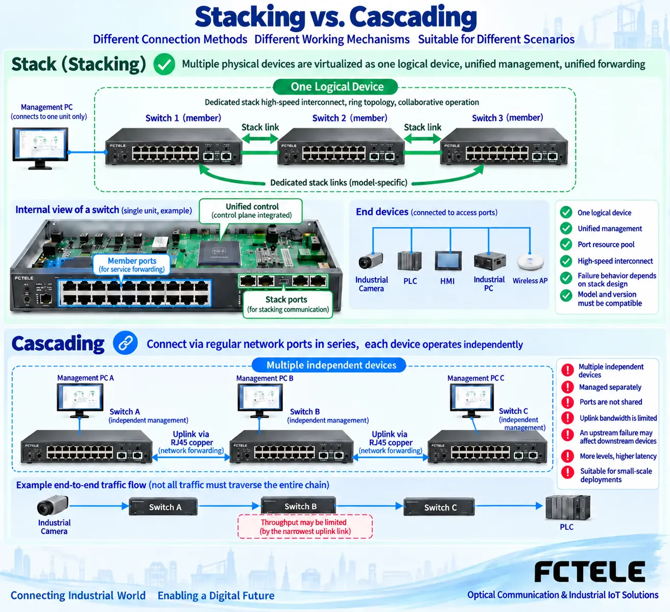
Multiple switches can all be connected to increase network coverage, but stacking and cascading describe different ways of organizing them. Common hardware stacking uses supported dedicated interfaces and corresponding protocols to make multiple physical devices work externally as one logical device; cascading uses ordinary service ports to connect multiple independent forwarding nodes. When judging, first check the model, connection ports, and actual working mode. You cannot call it stacking just because the chassis are placed one above another.
Unified management software can list multiple independent devices in one interface, but that does not automatically equal true stacking. It may only centrally display and deliver configurations, while each switch still has independent control and failure scope. Likewise, connecting two optical fibers or enabling link aggregation will not naturally merge the control systems of two devices. Appearance, management interface, and technical functions must be checked separately.
How stacking organizes control and ports
Take a stacking system that supports the corresponding functions as an example: members exchange information through stacking connections, determine control roles according to platform rules, and bring ports from different chassis into unified configuration and forwarding organization. The external network can treat the entire stack as one logical switching node, but physical chassis, power supplies, interfaces, and internal resources still exist. It does not become one switching chip with unlimited capacity.
Control roles, backup mechanisms, member count, software version compatibility, and stacking topology all depend on the platform. A ring dedicated connection, cross-member aggregation, or failure takeover in one brand’s documentation cannot be directly treated as a capability of all industrial switches. Stacking interfaces of different series also cannot be interconnected just because the cable shapes match; before expansion, the supported member combinations and upgrade process must be checked.
How cascading lets data pass through uplinks
After two independent switches are connected using Ethernet electrical ports or compatible optical ports, cross-device communication needs to pass through the corresponding uplink. Each node decides the exit according to its own forwarding table, VLAN, and port status; devices still need to maintain configuration and management addresses separately. After adding a third switch, services at the two ends of the link may pass through intermediate nodes and multiple uplinks. The actual path determines capacity and failure impact.
If the available capacity of a certain uplink is less than continuously aggregated traffic, caching can only temporarily absorb part of the burst and cannot eliminate a long-term bottleneck. The old article compared 100 Mbps with fixed stacking backplane numbers, which cannot be used for all current models. You should record the rate of each segment, bidirectional load, packet size, and service destination, and verify with real configuration and traffic rather than only comparing the number of chassis.
What capabilities does link aggregation add?
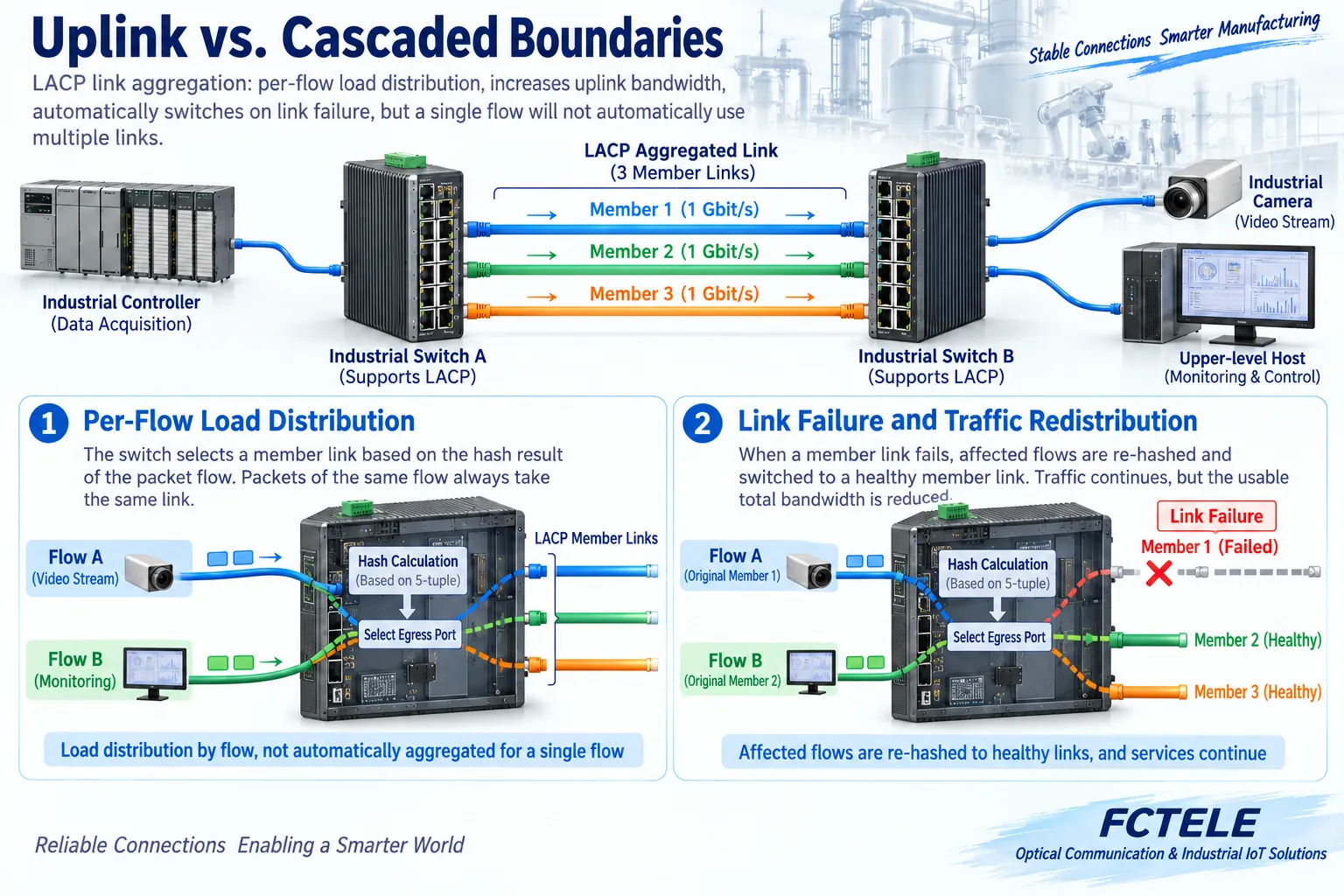
Devices that support link aggregation can organize multiple member connections into one logical link in order to distribute traffic and handle member failures according to the implementation. Common distribution methods select members based on relevant fields of the session, so one session usually does not automatically occupy the full capacity of all members at the same time. The sum of the nominal rates of several uplinks does not equal the rate that any single file transfer can achieve.
Whether members are reselected after a failure, which flows are affected, and whether the remaining total capacity is sufficient all need to be tested against the specific model and service. Multiple ordinary parallel cables cannot be directly treated as aggregation; uncontrolled Layer 2 loops may cause broadcast storms. Aggregation, spanning tree, and stacking solve different problems. When configuring, you should clarify the role each plays in the topology to avoid different protection mechanisms conflicting with each other.
Simpler management does not mean a smaller failure scope
One logical device can usually simplify unified configuration, but it may also bring multiple members into a common software and control scope. Independent cascaded devices have more distributed configuration, but may also make partition maintenance easier. Either way, power, uplinks, control roles, and upgrades all affect services. You cannot prove high reliability with one unified management address, nor assume that more members are necessarily safer.
For expansion, confirm whether adding a new member or new node online affects existing ports, whether a version change requires a restart, and whether an independent recovery entry is retained. If dual power supplies are connected to the same unreliable power branch, a common failure point still exists; multiple optical fibers running through the same conduit have a similar problem. Redundancy should be implemented in actual paths, not just by drawing repeated icons on a topology diagram.
How FCTEL products are used for this kind of planning
The documentation for the FCTEL model 2241 managed four-optical eight-electrical Layer 3 switch lists multiple optical and electrical interfaces, VLAN, link aggregation, and network management functions, and can be used to check independent switching nodes and uplink planning. The aggregation or ring network functions listed on the product page do not constitute proof that this model supports dedicated hardware stacking; without corresponding interfaces, manuals, and compatibility tables, it should be designed as an independent device.
When selecting a model, list the number of access ports, uplinks for each segment, expected concurrent traffic, and maintenance requirements, then ask the supplier to confirm the actual firmware, aggregation member conditions, and failure recovery behavior. When you need one logical device to manage multiple chassis, you must explicitly require true stacking capability; when you only need remote port expansion and coverage distance, check cascading capacity, optical module pairing, and service boundaries.
Acceptance should make topology changes actually happen
First use a small number of terminals to verify same-VLAN communication across nodes, check uplink tags, management, and counters, then gradually increase concurrent load. For aggregation testing, observe both the distribution of multiple sessions and the actual exit of a single session. Schedule member or uplink failure tests in an isolated environment or maintenance window, and do not randomly unplug cables in a production network to create loops.
Record the control state, port state, available capacity, packet loss, and application recovery before and after the failure, and check whether the configuration is retained after a restart. The basis for truly completing acceptance is that the target service meets requirements under normal, expansion, and specified failure conditions; it is not being able to log in to a web page, see a few member names, or simply light up all newly added ports.
Documentation note: The principle diagrams have been checked for technical content and are used to explain general mechanisms. They are not product photos or measured records. Specific interfaces, modes, and capabilities are subject to the selected model, version, and on-site verification.
Verification materials: Cisco switch stacking mechanisms
Cisco stacking and independent switching device management
FCTEL managed four-optical eight-electrical Layer 3 switch
FCTEL industrial switch categories
Related technical topics: How SDH MSTP multi-service platforms are accessed: service mapping, interfaces, and clock verification How to distinguish E1, channelized E1, and PRI: time slots, signaling, and access acceptance How MEMOBUS serial ports run over fiber: message transparent transmission, transmit/receive timing, and device verification
Translated from the Chinese technical article. Source first published: 2021-12-06. Source last revised: 2026-10-13T01:08:12+08:00. Read the Chinese source
