


First ask what is being transmitted and received, not just whether it is industrial-grade
A transceiver means a device or component with both transmit and receive functions. The name alone cannot determine what it transmits or where it connects. In industrial projects, it may refer to an RS485 chip on a circuit board, a wireless module with an antenna, a pluggable optical module, or a complete fiber optic unit with its own power supply and interfaces. When purchasing, first clarify the level, signal, and devices at both ends to have comparable specifications.
Older articles mixed wireless communication, serial port chips, and fiber optic single-mode/multi-mode into the same category, and even derived power consumption and market trends from fiber type, which easily leads readers to buy the wrong item. Chips, modules, and complete units can exist simultaneously in one system, but their working boundaries differ. This article explains these names based on signal changes, without reducing all transceivers to wireless devices or assuming they share the same circuit structure.
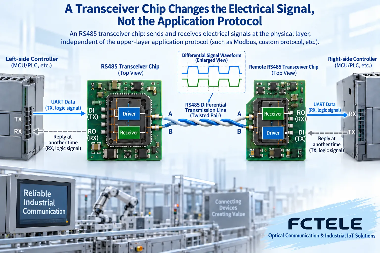
Interface chips convert logical data into electrical signals on the line
Taking the common RS485 interface as an example, the controller provides logical data, and the driver circuit converts it into a differential signal suitable for the line; the receiver circuit then compares the voltage relationship on the line to recover the logical state for the local controller to process. The chip completes this part of the electrical work on the circuit board. Peripheral power supply, protection, interfaces, and software still require system design. A bare chip cannot be directly connected to any site.
Differential reception focuses on the difference between two signal lines, which helps handle common disturbances within a certain range, but it does not mean any noise or ground potential difference can be eliminated. RS485 specifies the electrical interface, not what service message each device transmits. Even if the levels at both ends can connect, you still need to verify the protocol, rate, and transmit/receive timing; changing a transceiver chip will not automatically translate communication protocols.
Transmit and receive both exist, but not necessarily at the same time
A common two-wire half-duplex bus allows transmission and reception to use the same pair of signal lines at different times. The controller enables the driver according to rules, releases the bus after sending, and only then can the other end reply. If multiple nodes drive simultaneously, contention occurs. Full duplex usually requires separate transmit and receive lines. The specific interface and control are determined by the device documentation; you cannot infer bidirectional concurrency from the word transceiver.
When evaluating interface components, look at the logic-side power supply, electrical-side conditions, load, direction control, and failure behavior. Choosing a chip solves hardware interface design; choosing a complete unit solves site access and deployment. The test tools are also different. Circuit waveforms, terminal application responses, and complete unit immunity correspond to different evidence. You cannot use a chip’s voltage rating field to replace the full device capability.
Wireless modules add a radio frequency link and communication organization
Wireless transceiving involves sending information to a radio frequency link and then recovering information from the received radio frequency signal. The module may also integrate a controller, protocol stack, and application interface; the specific scope depends on the product. TI’s wireless microcontroller documentation can help understand this level, but its parameters cannot be taken as the specifications of a specific FCTEL wireless unit, and even less can it be said that fiber optic transceivers also have wireless capabilities.
Having an antenna does not mean any two devices can communicate; they also need to match frequency band, modulation, protocol, and operating configuration. Site coverage and actual throughput are also affected by deployment conditions. If the requirement is ready-made serial wireless transmission, look for a complete unit that supports the corresponding interface and transparent or protocol mode; if the requirement is to develop wireless hardware yourself, you need modules or chips and supporting development conditions.
Ethernet fiber optic complete units change the transmission medium
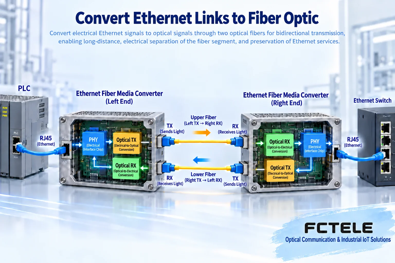
The commonly called industrial fiber optic transceiver often has an Ethernet electrical port on one side and a fiber optic port on the other. The electrical port physical layer receives line signals, suitable circuits process the data, and the optical transmitter sends information into the optical link; the remote optical receiver and electrical port circuit complete the reverse recovery. Actual devices may include buffering and switching functions, or may use other implementations, which must be confirmed by the specific structure.
The optical path allows long-distance segments to use optical propagation, but it does not automatically become a router, video decoder, or industrial protocol gateway. When the terminals at both ends are originally Ethernet devices, you can verify the corresponding electro-optical extension solution; if the original signal is RS485 or analog video, choose dedicated equipment suitable for that signal. The same fiber optic connector cannot prove service format interoperability.
Single-mode, multi-mode, and power consumption are different selection conditions
Single-mode and multi-mode describe the propagation conditions of the optical fiber and need to match the module, wavelength, reception range, and link loss. They are not classifications for wireless transceivers or RS485 chips. You cannot declare a device more power-efficient just because of the word multi-mode, nor can you take the nominal distance as the entire reception capability; actual complete unit power consumption is also related to ports, processing circuits, optical modules, and power supply efficiency.
Dual-fiber usually carries two directions separately, with local transmit connecting to remote receive; single-fiber bidirectional uses matching transmit/receive wavelengths and device configuration. Pluggable modules also require checking the host interface and supported standards. The same form factor can contain different service modules, so the procurement list should specify the module identity, complete unit identity, and compatible opposite end at the same time, rather than only providing a photo of the optical port.
What level of capability does the FCTEL industrial managed transceiver provide?
The one-fiber one-electrical 100M details in the FCTEL industrial managed transceiver category belong to a complete unit with site interfaces and independent power supply. The page lists local and remote status viewing, power failure detection, and related power protection capabilities. These can help maintenance personnel distinguish link disconnection from opposite-end power loss. It is not a directly interchangeable commodity with an interface chip soldered on a PCB.
The details do not have a model field sufficient to confirm the complete ordering model; procurement needs to specify the exact hardware, optical port, and power configuration. Network management facilitates configuration and observation, but it does not automatically increase the physical port rate, nor does it mean support for arbitrary protocol conversion. Dual power supplies and alarms should be accepted based on actual wiring and management methods; you cannot infer from one function name that the entire system has no common failure point.
Select by task, then accept by actual service
For example, to extend a controller that already provides an Ethernet interface to a remote equipment room, first verify the electrical port rate, optical path conditions, power supply, environment, and maintenance requirements; if the controller only has RS485, first decide whether to use serial optical transmission or serial network access. This is a requirement analysis example, not a customer case. The same long-distance goal may require different product objects.
For complete unit acceptance, first perform a compatible short-link loopback test, then connect to the site line, recording negotiation status, optical power, port errors, and actual application response. Chip design requires corresponding electrical measurements and complete unit integration verification. At delivery, clearly state the device level, input/output, pairing conditions, and test scope, so subsequent maintenance personnel know whether to check the electrical interface, optical link, wireless connection, or service configuration.
Documentation note: The principle diagrams have been checked against technical content and are used to explain general mechanisms. They are not product photos or measured records. Specific interfaces, modes, and capabilities are subject to the selected model, version, and site verification.
Verification materials: TI RS485 Interface Design Guide
TI DP83867IR Ethernet Physical Layer Chip
TI CC1312R Wireless Microcontroller
FCTEL Managed Industrial 1-Fiber 1-Electrical 100M Transceiver
FCTEL Industrial Managed Transceiver Category
Related technical topics: How China No.1 Signaling Works: Line Status, Number Interaction, and Differences from No.7 Signaling How to Maintain and Protect an OEO Fiber Repeater: Two Optical Paths, Local Power, and Fault Location
Translated from the Chinese technical article. Source first published: 2020-07-03. Source last revised: 2026-10-13T02:05:34+08:00. Read the Chinese source
