


Whether one pair of serial fiber modems can connect multiple instruments depends on the serial electrical interface, the device forwarding capability, and the upper-layer communication method. Common RS485 two-wire polling can let multiple slaves reply in turn, but the fiber modem will not automatically assign addresses to instruments, nor will it resolve simultaneous transmission conflicts. This article discusses multi-device collection and does not generalize multi-point capability into any arbitrary topology.
Multiple devices sharing a line does not mean they speak at the same time
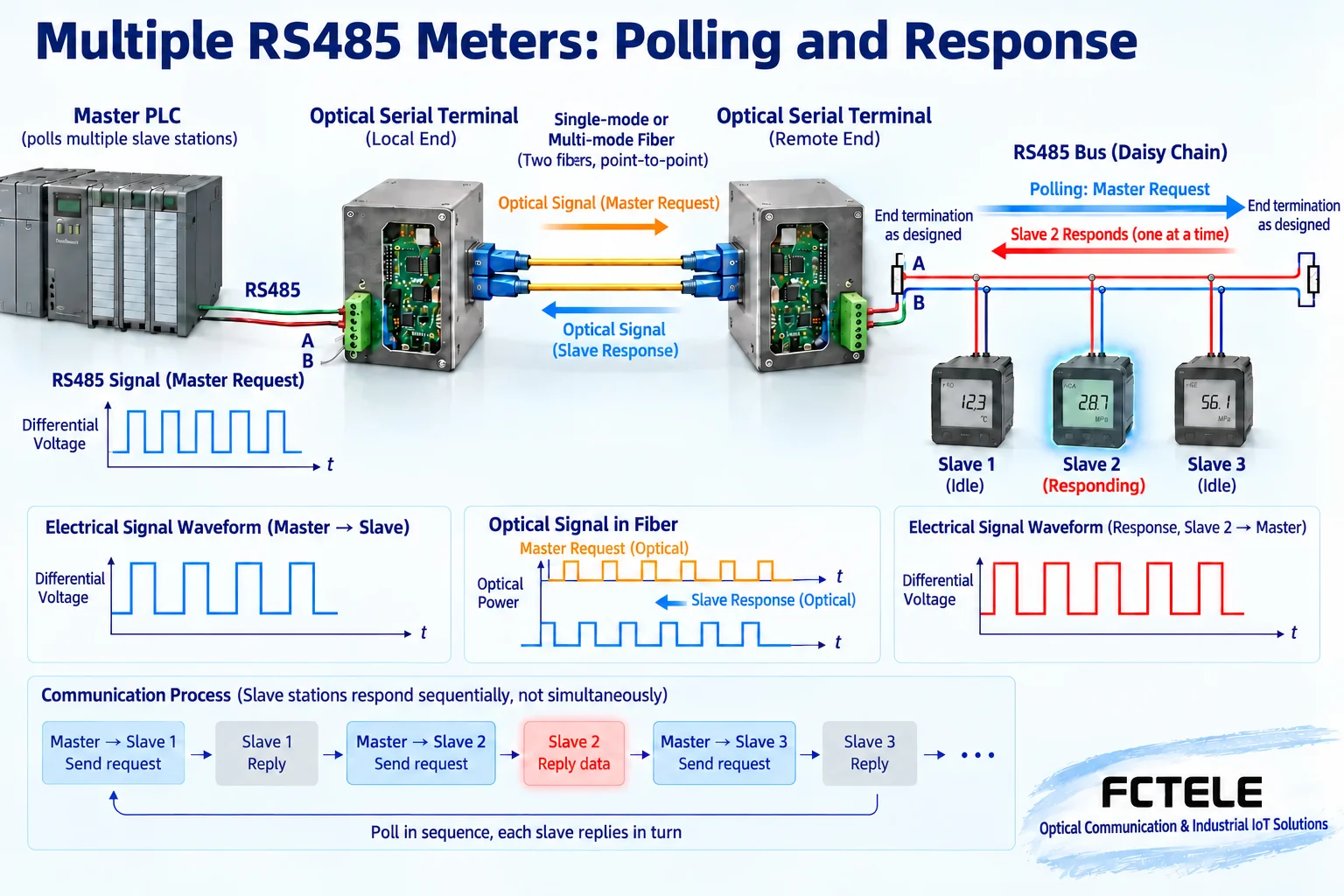
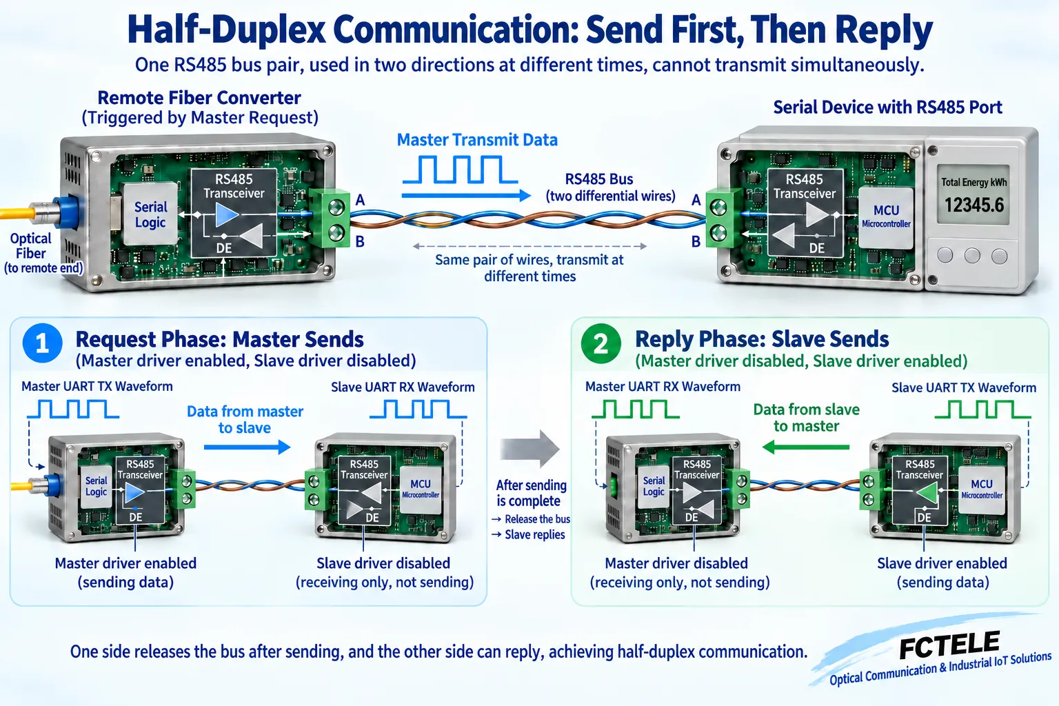
Two-wire half-duplex means transmission and reception take turns using the same pair of signal wires. The master sends a query for a specified address, the corresponding slave replies at the agreed timing, and other slaves stay silent. It is like sharing one speaking channel; the analogy only helps understand taking turns, but a real system is still controlled by the protocol, timing, and drivers, and no one automatically moderates all devices.
If two nodes drive the bus at the same time, the received content may be wrong. Electrical multi-point capability does not equal message arbitration capability; duplicate addresses or multiple masters lacking coordination can both cause conflicts. Even if each instrument works normally when connected alone, it may still fail after all are connected. First confirm the allowed number of masters and protocol roles, then consider node scale.
What the fiber modem extends is the entire interaction path
In a typical remote transmission scheme, the near-end master connects to the near-end fiber modem, the fiber connects to the far-end fiber modem, and the far-end RS485 bus connects multiple instruments. The master request travels through the optical link to the far end, and a certain slave reply returns along the reverse direction. The fiber modem is responsible for forwarding on the corresponding interface; it does not automatically become an application-protocol master just because multiple instruments are connected.
An ordinary point-to-point optical port cannot be directly expanded into an arbitrary multi-point network using passive optical splitting. The optical-side topology of the optical transceiver and the electrical-side multi-point nature of RS485 are two separate issues. If multiple remote branches, a ring network, or concentration are required, choose dedicated equipment that explicitly supports them and check the business logic. Do not treat one RS485 multi-point description as proof that the optical port can branch arbitrarily.
Bus wiring and load determine the electrical conditions
RS485 often uses a trunk and short stubs. Terminal matching is set according to cable characteristics, rate, length, and the device manual, and usually focuses on both ends of the trunk. Do not blindly add termination resistors to every instrument, or the load may increase. Overly long stubs can affect reflections, and arbitrary star connections may not meet on-site requirements. Signal reference and shielding should also be checked according to the electrical design.
The allowed number of nodes is related to transceiver load, biasing, and topology; not every system has one unified guaranteed number. If a device page gives a node count, still confirm the test and ordering conditions and match it with the actual instrument capability. The electrical interface being able to connect more nodes does not mean the collection cycle is sufficient to poll more nodes; the two capacities should be evaluated separately.
Automatic direction control must give up the reply opportunity
After the fiber modem receives master data, it drives the bus at the far end. After transmission is complete, it needs to release the drive at the appropriate time so that slaves can reply. Automatic direction control helps complete this process, but judgment and release must adapt to the real data rhythm. Releasing too early may cut off the end, and releasing too late may conflict with a fast reply; the specifics are determined by the model design and configuration.
Verify the complete request, the last character, and the earliest reply, rather than only looking at whether most queries succeed. Different baud rates, short and long messages, and burst conditions may produce different behavior. When a device claims support for a certain application, it still needs to be confirmed with the current firmware and terminal testing; one instrument passing does not guarantee all protocols, all nodes, and all reply speeds.
Neither addresses nor serial parameters can be missed
Each slave address must comply with the protocol and avoid duplication, and the data bits, parity, and stop bits must also be consistent. Two devices with the same address may reply at the same time, and what the master sees is not two distinguishable pieces of data. Automatic baud rate detection cannot automatically change addresses, nor is it responsible for repairing incorrect application parameters; the configuration list should be saved instrument by instrument.
During troubleshooting, first leave one slave, confirm the original short-cable communication, then add the optical link, and finally add nodes one by one. If an abnormality appears after adding a certain unit, check the address, wiring, terminal load, and power supply instead of immediately increasing the timeout. Adding gradually helps locate changes and also makes rollback easier; formal system operations need to be carried out in an approved window.
The collection cycle must include waiting and retries
Each polling round includes transmission time, propagation, direction switching, instrument processing, and reply, and there may also be intervals required by the protocol. When polling multiple units, these times accumulate to determine the refresh cycle. If a failed node keeps waiting until timeout, it will slow down subsequent nodes; unlimited retries cannot prove reliability and may instead prevent normal devices from getting a chance to update for a long time.
Waiting and retries can be set according to project requirements, isolating continuously failing addresses and reporting status, but this is usually the responsibility of the master software, not something an ordinary fiber modem implements automatically. Acceptance should record the complete polling cycle, slowest response, and recovery behavior in both success and failure cases; the maximum serial rate cannot be directly converted into a guaranteed system refresh frequency.
The product’s multi-point description must be confirmed by version
The Feichang FCP-D1 function description mentions RS485 polling and customizable node support, which can serve as a clue for a multi-device collection candidate, but it is not a guarantee for all nodes in an actual system. Please verify with the specific ordered version, load, and terminal documentation. Automatic direction control also does not mean the fiber modem understands instrument addresses or performs protocol arbitration; the master’s responsibilities still need to be clear.
The rate statements in different places on the page are not completely consistent. During procurement, obtain the current specification sheet and confirm both the minimum rate and the actual data mode. Optical-side pairing, interfaces, and power should be checked independently, and general parameters from old articles should not be reused. If multiple independent serial ports are required, the number of channels should be clearly specified; a single multi-point bus does not equal multiple independent channels.
The final check is the complete business, not just lights on
Suppose a group of water meters needs to be read periodically. The test should verify addresses and known readings one by one, then perform continuous polling for the agreed duration. Save errors, timeouts, responses, and collection cycles, and do not treat occasionally reading one piece of data as the whole group passing. Link disconnection and power recovery need to be arranged under safe conditions, and production control must not be interrupted arbitrarily.
The check also includes bus endpoints, stub length, terminal fastening, and power protection. The middle section of the fiber is non-conductive, but the end RS485 still must meet electrical conditions. Only when the electrical load, protocol roles, direction switching, and time budget are all suitable can one pair of fiber modems possibly stably extend polling for multiple instruments, rather than solving the problem by enlarging a promotional number.
References: TI RS485 Design Guide ; Feichang FCP-D1 serial fiber modem product information The images are general principle illustrations; configuration and testing are subject to the actual delivered manual.
Translated from the Chinese technical article. Source first published: 2023-12-22. Source last revised: 2026-10-13. Read the Chinese source
