


First, draw where along the path the fault occurs
TDM over IP lets traditional circuits pass through an IP network. When troubleshooting, you should separate the local E1 interface, the packet transport, and the remote circuit recovery. It is not a tactical data routing protocol, and RIP is not a feature that every gateway must enable. First confirm which circuit you are checking, which two ports are involved, and which set of remote mappings is used, so you do not treat the status of other services in the same chassis as evidence for this circuit.
The smallest path is terminal, left gateway, IP network, right gateway, and remote terminal. In practice there is also power, clock source, and management path. The diagram only draws one direction; troubleshooting also needs to check the reverse direction. Recording when the fault appeared, whether it changes with load or path, and which channels are abnormal at the same time is more likely to leave useful clues than starting with a factory reset or reinstalling firmware.
Management access is not the same as service continuity
A management web page or ping working normally only shows that part of the conditions for the relevant management path and service are met. The service may use different ports, VLANs, or target mappings, and may also be limited by other rules; being able to manage does not prove that the transport packets have reached the correct receiving channel. Conversely, failure of management access does not necessarily mean every circuit has stopped working; you should observe the terminal and service status separately.
After confirming the device identity, current address, maintenance entry point, and account, save the configuration, model, and firmware records. When on-site work is needed, first prepare an approved maintenance window and a rollback plan; do not shut down all security rules at the same time just to test connectivity. The management port, service Ethernet port, and E1 interface have different roles. Even if they look like RJ45, that does not mean the cables and pins can be mixed freely.
For local E1, check the signal first, then the service mode
LOS usually means the relevant interface cannot detect a valid line signal. Check it together with the cable, port, terminal power, and interface conditions. Framed services may also show loss-of-frame and other states, so you need to check the frame structure, signaling, and settings at both ends. AIS can mean an upstream abnormality is being indicated downstream; seeing it should not lead you to conclude that the local network port is damaged. The meaning of an alarm and how to handle it must be based on the device documentation and the service mode in use.
E1 lines have interface conditions such as balanced 120 ohm and unbalanced 75 ohm. You should check the actual equipment and adapter components, not just whether the plug can be connected. A normal line test also does not prove that the timeslots are sent to the correct user. The objects to check for an unstructured full circuit and for structured channel mapping are different; do not apply all alarms and settings to every mode.
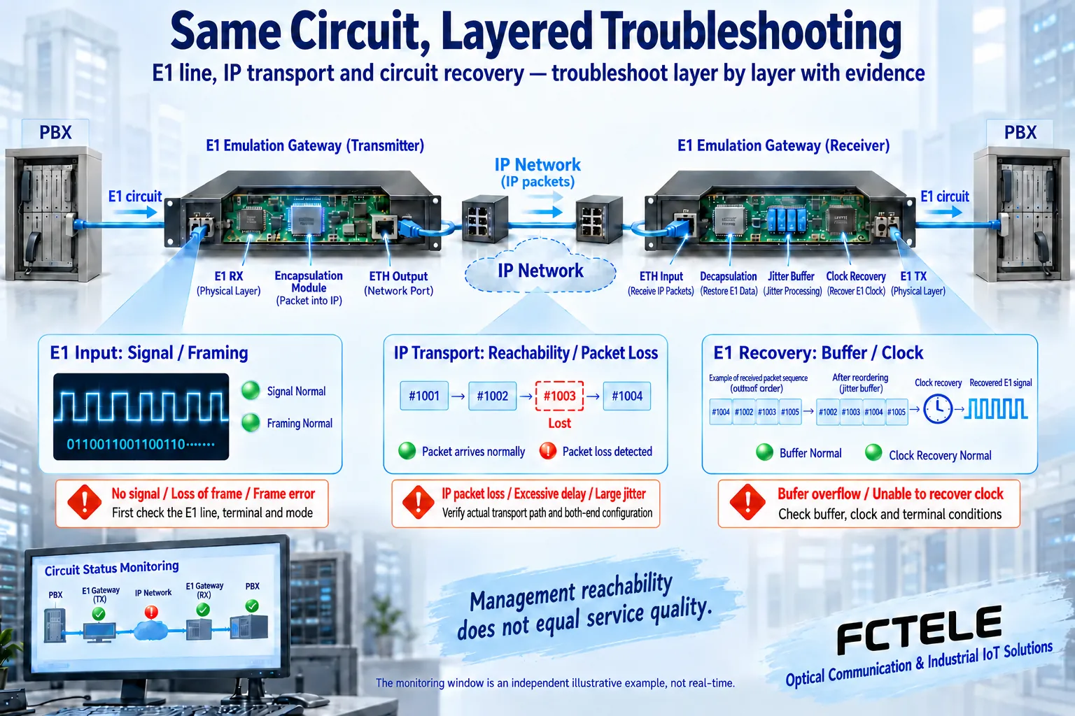
On the IP side, look at the packets that actually carry the service
Check the relevant addresses at both ends, the forwarding path, allowed ports, VLANs, and packet length conditions. Check according to the encapsulation and configuration actually supported by the product; do not infer from the name that all gateways use the same transport protocol, and do not copy the default ports of other vendors. When service is not received, you should distinguish between the sending side not forming packets, restrictions along the way, and a mismatch in the receiving side mapping.
When suitable monitoring capability is available, compare the packet counts, order, late arrival, and loss status between sending and receiving, and check the measurement time. Cumulative counters should be understood together with two readings and the interval; clearing or restarting changes the statistics. Packet capture location also has limits: seeing transmission on one side does not prove the far end received it; an ordinary computer not seeing a certain packet also cannot directly prove that the network never forwarded it.
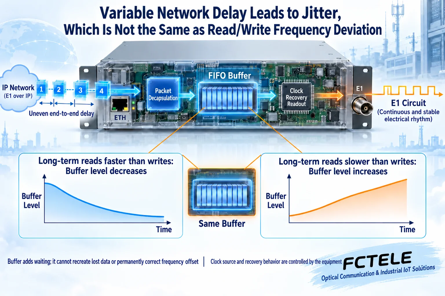
Look at arrival variation and long-term frequency offset separately
Packet networks queue, so packet arrival intervals may vary. The receiving end temporarily stores data in a buffer and then reads it out according to the required clock; when packets arrive later than allowed or are lost, the original content cannot be restored from the buffer out of thin air. The device may produce substitute output or a corresponding alarm, and the specific behavior must be checked. The queue and waveform in the diagram are only general mechanisms, not measured results.
If the long-term read rate is faster than the write rate, the water level may gradually drop; if the long-term read rate is slower than the write rate, it may gradually pile up. This frequency relationship is not the same problem as short-term uneven arrival. You should check the clock source at each end, the master-slave relationship, and the behavior after reference failure. Setting NTP time for the management system does not prove that E1 line frequency recovery has met the requirement, and simply increasing the buffer cannot permanently fix a continuous frequency offset.
Parameter adjustment only verifies one hypothesis
First establish a baseline under representative load, then change one relevant condition at a time within the range allowed by the manual, and record the alarms, waiting, and actual service before and after. A deeper buffer may accommodate some arrival variation, but it also increases delay; a larger payload packet may reduce part of the encapsulation ratio, but it also increases collection waiting. You cannot set both values to maximum and then call an accidental recovery a permanent fix.
Path switching, shared egress congestion, or changes in a security tunnel can all change the transport conditions. QoS can arrange priority, but it does not increase sustained egress capacity; the added length and overhead of a tunnel also need to be checked. After the network becomes reachable again, continue to check E1 and the real service; do not use one no-load ping result to replace the bit errors, alarms, and application performance of a loaded circuit.
Use loopback capability with Feichang Technology gateways
The Feichang Technology FCT-E1 and FCT-E4-M details list maintenance directions such as clock recovery, configurable packet length, VLAN, E1 packet loss indication, and local/remote E1 loopback. The FCT-E4-M also provides multiple target IP and port mapping, so the remote ends of four circuits can be checked one by one. These descriptions help determine which states to check; they do not mean that all standard diagnostic counters or commands listed on the web page have been implemented.
Loopback forms a return path for the relevant test range and is suitable for helping locate faults within a confirmed boundary, but it may occupy or interrupt service. Before testing, check the loopback location, direction, and whether it bypasses other links; operate according to the manual during a maintenance window, then exit and restore the configuration afterward. One loopback passing only shows the result within the range covered by that test; it cannot automatically prove that the public network transport, all channels, or the terminals at both ends are normal.
From small-range testing back to the full path
Under isolated test conditions, first select one circuit and a matching terminal to complete a local or short-path test, check the interface, frame, mapping, and timing, and then connect back to the actual network. Observe no-load and target load separately, and confirm that the status still meets requirements after other channels are added. When a test pattern is needed, use suitable instruments and an approved method; do not inject it directly into a production circuit, to avoid affecting telephone or data services.
If it is abnormal only on the actual network, save the port, packet, buffer, and alarm records at that time, and narrow the range segment by segment along the path; if the short path also fails, then check the terminal, interface settings, clock, and hardware. Replacing equipment or upgrading firmware should have model matching, a change basis, and rollback, rather than being the first troubleshooting step. After recovery, verify the real service in both directions at the same time, not just that the red light has disappeared.
Deliver a fault record that can be reviewed
Record the end-to-end topology, channels and remote ends, device versions, configuration, time, load, and each change. Write clearly the range that has been verified, the conditions not yet covered, and the observations after recovery, so the next maintenance person can judge. Alarms may have trigger and clear conditions; instantaneous abnormalities and continuous faults should not be mixed into the same statistic, and specific thresholds should be confirmed according to device capability.
The goal of troubleshooting is not to find a protocol that sounds more advanced, but to locate the specific problem in the local circuit, network transport, or remote recovery. When there is not enough evidence, keep the doubt and continue verifying layer by layer; once there is an improvement measure, retest with representative load and allowed variation. Only then can you explain why it recovered and what should be observed in the next maintenance.
Documentation note: The principle diagrams have been checked against technical content and are used to explain general mechanisms; they are not product photos or measured records. Specific interfaces, modes, and capabilities are subject to the selected model, version, and on-site verification.
Verification materials: Feichang Technology FCT-E1 single E1 circuit emulation gateway
Feichang Technology FCT-E4-M four E1 circuit emulation gateway
Feichang Technology TDM Over IP product category
RFC4553: Structure-Agnostic TDM over Packet
RFC5086: Structure-Aware Circuit Emulation
RFC4197: Circuit emulation, clock, and network requirements
E1 over IP encapsulation, buffering, and clock recovery
TDM over IP path changes and recovery acceptance
Related technical topics: What happens when TDM over IP encounters path switching: RIP boundary, reordering, and recovery acceptance How does E1 over IP work? Circuit emulation encapsulation, buffering, and clock recovery
Translated from the Chinese technical article. Source first published: 2024-04-16. Source last revised: 2026-10-13. Read the Chinese source
