


E1 is first a line system, not a service name
E1 refers to a type of digital line and interface system with a nominal rate of 2.048 Mbit/s, and it can carry different digital services. Channelized E1, a certain data interface configuration, and E1-based PRI telephone access may use related physical ports in actual equipment, but they describe different layers. When asked whether they can interconnect, first list the line, electrical, frame structure, clocking, and service configuration; do not just answer that both sides say E1.
CE1 is often used to mean channelized E1, and its specific software functions and interface modes depend on the equipment. It is not a universal interface that can become any service just by changing the plug. The carrier delivery, user equipment, and intermediate transmission nodes must coordinate on the required conditions, and one cannot broadly say that all E1 lines are a certain framing or signaling mode.
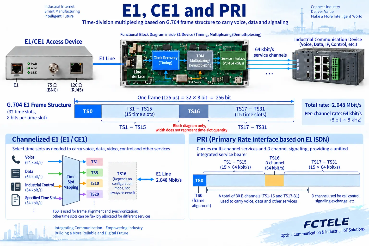
How 32 time slots produce a 2M rate
When the corresponding G.704 framing structure is used, one frame contains 32 time slots, each time slot has 8 bits, and there are 8000 frames per second. Therefore 32×8×8000=2048000 bit/s, which is 2.048 Mbit/s. When each fixed time slot position is used continuously, it corresponds to a basic data rate of 64 kbit/s. This is a calculation of the frame structure, and it does not mean that 32 user telephone calls can all be placed into it without distinction.
TS0 is time slot zero, and it carries frame alignment and the functions specified by the corresponding structure. It cannot be freely assigned as an ordinary user data time slot. Unframed E1 does not use the same set of user-configurable frame time slot semantics, and the test method must also change with the interface mode. Seeing that equipment is marked 2M does not by itself prove that it supports channelization, telephone signaling, or PRI calls.
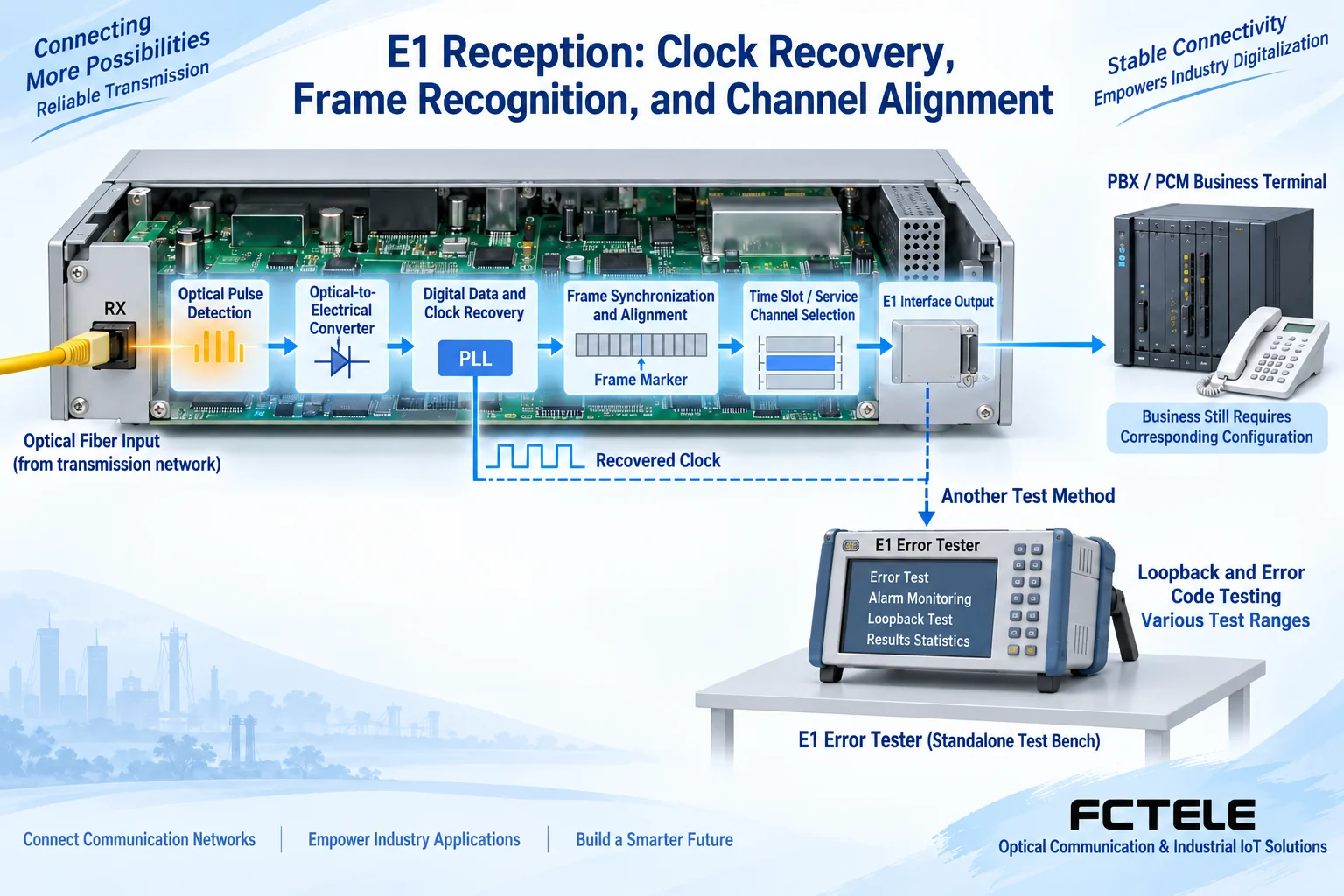
Line coding and user data format must also be distinguished. E1 commonly uses HDB3 line coding to help continuous transmission and clock recovery. It describes how digital states are expressed on the electrical line; it is not telephone codec or IP protocol. After the transmit and receive interfaces correctly recover the bits, the equipment must still identify the frame according to the service mode, select channels, and hand them to the corresponding terminals. One layer being normal does not prove that all later processing is correct.
Whether TS16 is used for signaling depends on the service
In the common 30B+D structure of E1 PRI, TS1 to 15 and TS17 to 31 correspond to 30 B channels, TS16 serves as the D channel to carry the corresponding signaling, and TS0 handles frame structure functions. The D channel is not the 31st ordinary telephone voice channel; it is used to organize call-related control. Supporting a physical E1 does not automatically mean the equipment has PRI signaling processing capability.
Other E1 services may use different signaling or pure data methods, and the use of TS16 should be checked against the corresponding specification, mode, and configuration. Old texts that uniformly claim CE1 can only use 30 time slots, or that all E1 is a certain telephone signaling, mistake service configuration for an inherent property of the line. It should be clear which time slots are data, which are reserved, and how the two ends and intermediate nodes correspond.
How channelized data is allocated
Equipment that supports the corresponding functions can organize specified time slots into data channels and plan basic capacity as N×64 kbit/s. N represents the number of time slots actually available and selected according to the mode, and it cannot exceed the range allowed by that configuration. Both ends need a consistent set of time slots, channel organization, and encapsulation requirements; merely setting N to the same number does not guarantee that the selected positions are the same.
Point-to-multipoint channel allocation also requires the intermediate network to correctly cross-connect the corresponding time slots or channels. One cannot merely divide one port into several groups at the user end and then have the far end automatically obtain several leased lines. The network service type, carrier delivery conditions, and user equipment capabilities jointly determine the solution; whether packet, aggregation, or telephone calls are supported should be checked separately in the documentation.
For example, if both ends plan to use four data time slots, record exactly which four positions they are, whether they form the same data channel, and the corresponding relationship in the intermediate network. Four times sixty-four gives the basic data rate of this group of positions, and the actual application may also be affected by encapsulation and terminal efficiency. One cannot treat both ends being written as four time slots as already matched, nor arbitrarily connect unused positions to another service without updating the full-link configuration.
How to check physical connections and clocking
75Ω coaxial is a common unbalanced method, and a 120Ω differential interface is a common balanced method. Impedance and pins should be matched according to the manuals at both ends. Some ports use DB or RJ connectors, but the shape is not sufficient evidence of electrical function. When impedance adaptation is needed, check the adapter design and the conditions at both ends; do not arbitrarily solder a wire and assume that a standard conversion has been completed.
Continuous E1 data also needs a suitable time reference. Equipment may support modes such as internal, external, or clock recovered from the received line, and the specific options must be consistent with the synchronization plan of the entire link. If both sides each use uncoordinated clocks, slips may occur; if they incorrectly wait for each other’s clock, stable activation may also fail. Record the actual source and the behavior when the reference is lost, not just the synchronization lamp.
Feichang Technology equipment should be placed in the correct part of the link
The Feichang Technology document for the FC2PM-O64/S64 multi-service equipment, numbered 78, can be used to check combinations of telephone, E1, and related service access. It provides a certain E1 access configuration, which is not enough to prove that any board supports channelized routing or PRI signaling. When purchasing, the user service, required number of E1 lines, interface form, and roles at both ends should be clearly specified and checked against the actual board and delivery manual.
If the task is only to extend E1 over optical fiber, a pair of optical transmission devices handles continuous data and timing recovery; when Ethernet needs to be carried over E1 or E1 needs to be carried into an IP network, that is a different adaptation solution. Telephone via PCM multiplexing occupies channels, while PRI uses signaling to control calls, and these are not the same interface role. Do not directly interchange these devices just because E1 appears in all of them.
How to prove that access is actually correct
First confirm electrical, framing, and clocking on a single short link, then verify the required channels or real telephone service, and then connect to the formal network. Record relevant states such as LOS loss of signal, LOF loss of frame, AIS, and CRC4, and interpret them according to the actual mode; do not force the same frame check onto unframed services. Bit error and application tests each have their own scope, and the results should be saved together.
Loopback can help locate a certain transmission segment, but passing a loopback test does not prove that normal bidirectional service has correctly reached the specified terminal. For channelized solutions, check the correspondence channel by channel; for PRI solutions, also verify calls in both directions, release, and the required functions. Save records of interfaces, modes, time slots, signaling, and clocking, so that when equipment is replaced later, activation faults will not be repeated because of changed default parameters.
Documentation note: The principle diagrams are used to explain general mechanisms and are not product photos or measured records. Specific interfaces, modes, and capabilities are subject to the selected model, version, and on-site verification.
Reference materials: ITU-T G.703 electrical characteristics of digital interfaces
ITU-T G.704 synchronous frame structures
Cisco E1 channel and PRI configuration mechanisms
Feichang Technology FC2PM modular telephone optical multiplexer
Feichang Technology modular multi-service telephone optical multiplexer categories
Related technical topics: How to distinguish switch stacking and cascading: logical device, uplink capacity, and fault boundary How SDH MSTP multi-service platforms are accessed: service mapping, interfaces, and clock checking How MEMOBUS serial ports run over optical fiber: message transparent transmission, transmit/receive timing, and equipment checking
Translated from the Chinese technical article. Source first published: 2021-06-22. Source last revised: 2026-10-13. Read the Chinese source
