


An optical link reports received power within its permitted range, yet the application still sees errors. A line that worked at a lower rate may also fail to qualify after an upgrade. Is more transmit power the answer? Not necessarily. A receiver needs enough light, but it also needs to distinguish changes over time. Dispersion-induced pulse spreading is one reason that receiving light and decoding information are different. We use a simple intensity-modulation model here; dispersion is not the cause of every error.
Optical power and signal shape answer different questions
Think of an optical pulse as a brief change in emitted light. The transmitter organizes such changes according to the communication code. The receiver converts the optical signal into an electrical signal and makes decisions at specified times. Brighter and darker levels are an introductory example, not a claim that every optical system uses simple on-off signaling.
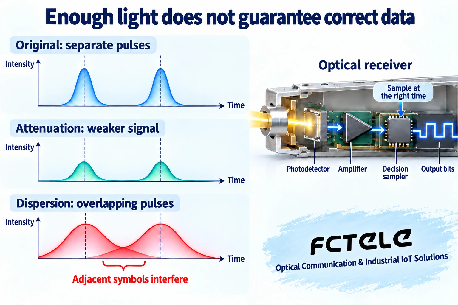
Average optical power describes how much light is received over an interval. It does not fully describe whether each change is distinguishable. Two waveforms can have similar average power but different edges and gaps between pulses. When one symbol extends into the next and affects its detection, this is intersymbol interference: neighboring symbols interfere in time.
Pulse spreading means a wider time interval, not a thicker fiber
After propagation through a length of fiber, energy originally concentrated in a short pulse may occupy a longer interval. This is pulse spreading. It concerns time, not glass diameter or packets queuing in a switch. Imagine people leaving together but arriving at different times. That analogy describes dispersed arrival times; it does not replace the physics of optical waves.
If neighboring symbols have enough separation, some spreading may be tolerable. At a higher rate, the time available for each symbol is generally tighter, so the same distortion may become harder to tolerate. Actual limits also depend on coding, transmitter, receiver and system design. A distance or rate alone cannot establish that errors are inevitable.
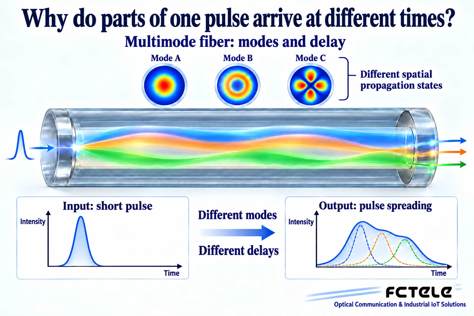
Multimode fiber: different modes can have different group delays
A mode is an allowed spatial propagation state of light in a waveguide. Multimode fiber supports several such states. They can have different group delays along the same fiber. Group delay is the time taken by a pulse envelope to traverse the path. When its components arrive at different times, their combined pulse can become broader.
Introductory explanations often use step-index geometric ray paths to explain this. Actual modes are not separate colored wires, and a fiber is not a hollow tube lined with mirrors. Common graded-index multimode fibers vary propagation conditions across the core to reduce differences in arrival time. The simple zigzag sketch therefore cannot calculate the performance of every multimode fiber. Launch conditions also affect which modes are excited.
Single-mode fiber avoids modal dispersion, not all dispersion
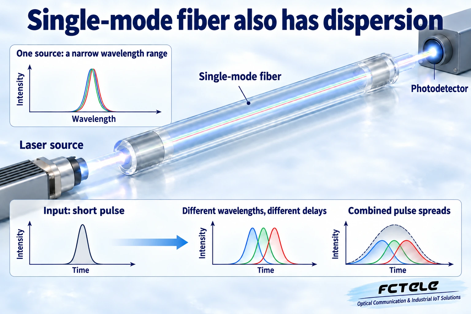
Under its specified operating conditions, single-mode fiber does not support multiple spatial modes, avoiding the modal dispersion described above. A real transmitter, however, does not emit exactly one infinitely precise wavelength. Center wavelength identifies the middle of a small spectral range, while spectral width describes its extent. Neither is the same quantity as the Ethernet data rate.
Different wavelength components can experience different group delays, spreading the arrival times within one pulse. Chromatic dispersion depends on material properties, waveguide structure, operating wavelength and source spectral width. Colors in the diagram distinguish components only. They do not represent visible operating light or mean that blue always travels faster than red. The relationship between wavelength and delay changes with wavelength band and fiber design.
Attenuation and dispersion need separate evidence
Attenuation principally describes reduced optical energy. Dispersion concerns differences in arrival time that change a waveform. The figure separates weaker pulses from broader pulses for clarity, but a real link can experience both. Spreading can also change a pulse peak, so a waveform height alone cannot identify the cause.
More transmit power does not automatically bring separated arrival times back together. Excess power can also exceed a receiver limit. Any equalization, error correction or dispersion-handling capability must be checked for the exact equipment and operating conditions. Do not assume an ordinary industrial optical module has the capabilities of a particular high-speed system. Polarization mode dispersion and other effects also exist; these introductory figures do not represent every optical impairment.
Check the complete optical system before reaching for a formula
Record both devices, optical modules, fiber type, length, operating wavelength and actual rate. Check supported fiber and distance in the module documentation, along with the installed link requirements at that rate. For multimode links, confirm the fiber grade and applicable bandwidth requirements. Physical connector compatibility does not make arbitrary fibers, modules and launch conditions interchangeable.
FCTEL industrial optical communications documentation provides a starting point for checking real interfaces and connections. For example, the linked managed-switch documentation lists copper and SFP optical interfaces. The actual link still needs modules matched to its fiber and operating conditions. An SFP slot does not automatically remove fiber dispersion. A distance rating must be used with its specified module, fiber and test conditions.
Also inspect the physical link. Dirty end faces, splice losses, bends and loose connections remain possible causes of failure. Bend loss concerns guidance and energy loss; this article concerns arrival times and waveform distortion. Both can occur together, but each needs appropriate evidence.
Changing a multimode link to single-mode is not simply replacing one patch cord. Check both optical interfaces, operating bands and link requirements together. Connecting a single-mode module to arbitrary multimode plant and reading its power is not a quality assessment. Before upgrading the rate, review the complete installed plant and its test records. A previous successful low-rate connection is not a permanent qualification.
Verify the cause instead of turning a suspicion into a diagnosis
Keep time-correlated records of received power, error counters, link state and application failures. A power meter assesses optical transmission level; one reading cannot diagnose dispersion. Ordinary time-domain reflectometry helps locate link events and is not a universal direct chromatic-dispersion instrument. Where dispersion or waveform quality needs assessment, use an appropriate method and, when necessary, personnel with suitable instruments and experience.
During an authorized maintenance window, compare against a known-good, specification-matched module or link, changing one condition at a time. Improvement initially associates the problem with the changed condition; connection cleanliness and other equipment differences still need to be excluded. Do not change a production link rate casually or look into an optical port. Documenting test conditions is more useful than recording only that optical power was normal.
Final acceptance should cover the real application load and required stability, not merely an illuminated link indicator. The useful idea is straightforward: optical energy must arrive, and the receiver must distinguish information at the right times. Match the system, inspect the plant and confirm with evidence before treating additional launch power as a cure.
Technical references: Corning: Chromatic Dispersion, AEN 19; Cisco: fiber dispersion; FOA: optical fiber; FOA: dispersion testing; Cisco: receiver decisions and errors. Related resources: FCTEL Technical Articles and FCTEL industrial optical communications documentation (Chinese). Original AI-assisted illustrations explain generic principles, not product internals or measurements.
