


INDUSTRIAL INTERFACES / POWER DOMAINS
Why can a signal keep an unpowered rail alive?
Some ordinary inputs provide a clamp path from the signal to the supply rail. If a remote driver remains high while the target supply is disconnected, current can charge the rail through that path and return through shared references. Partial voltage does not prove normal operation. Check the actual pin specifications and complete circuit; protected interfaces may behave differently.
01 · Follow the injection path
An ordinary unprotected input may forward-bias its rail clamp when its source remains high and the target supply is off. A return path is also required.
02 · Observe two signals
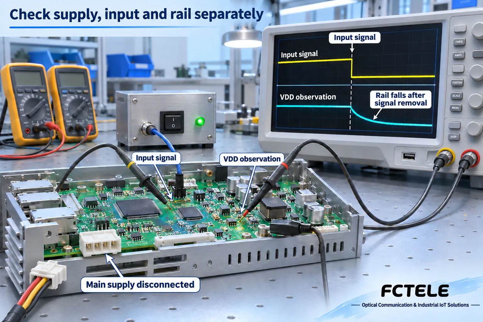
In a controlled observation, removing the input may let the rail fall. This supports a supply contribution, not a complete diagnosis or a measured performance claim.
03 · Check powered-off isolation
An open contact illustrates high impedance only. Actual IC leakage is specified for named pins, input voltages, temperatures and supply combinations.
Map every source
List main supplies, USB, signal drivers and instrument connections.
Observe input and rail
Change one permitted source at a time on a controlled bench.
Read the conditions
Verify Ioff, supply combinations and affected pins in the actual manual.
Selection and verification checklist — expand
| Check | What to confirm | How to verify |
|---|---|---|
| Boundary | Internal logic versus external port | Model manual and documented conversion stages |
| Off state | Leakage and rail contribution | Named pins and zero-supply specifications |
| Recovery | Reset and valid business data | Repeat the documented supply sequence |
Disconnect a communication board’s main supply, and its supply rail may remain above zero. Remove the debug signal cable, and the residual voltage disappears. A signal pin may be feeding current into circuitry intended to be off. Understanding this back-powering requires following the input, protection junction, supply rail and return path, while distinguishing an ordinary logic interface from one with specified powered-off protection. This article explains general board-level mechanisms; it does not diagnose any particular Feichang product.
Separate the main supply from signal connections
Industrial communication systems often connect several power domains. A controller may remain on while a communication daughterboard shuts down. A maintenance computer and debug adapter may stay attached after the main system supply is disconnected. Opening one supply interrupts its intended power path; it does not establish that every other conductor carries no energy. A signal output is driven by a circuit powered at the other end.
Start with a shared-ground, low-voltage logic example. This logic input is not a terminal that can accept external RS232 voltages directly. An internal UART signal, a board header and a complete RS232 or RS485 port are different electrical boundaries. External ports may include level conversion, isolation and protection networks. Matching interface names do not establish matching internal structures.
Assume the source board is powered, the target board’s main supply is disconnected, the source output remains high and both boards share a reference ground. To establish back-powering, identify both the entry point and the path returning to the source. A high-level label alone does not make a sustained current loop. Instruments and additional cables may also create return paths that were initially overlooked.
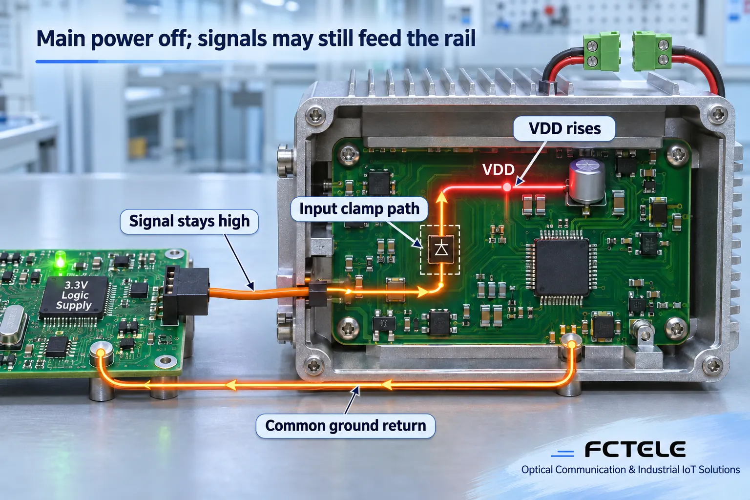
How current moves from an input into a supply rail
For some ordinary IC inputs, part of the protection structure can be approximated as a clamp junction between the input and supply rail. During normal powered operation with the input inside its allowed range, that path is not intended to supply continuous power. When the target loses power, its rail falls while the remote input remains higher. The relevant junction may become forward biased. Current then enters through the signal pin, reaches the target rail and returns through circuit loads and the reference connection.
Although the signal’s intended purpose is information, its driver can deliver energy under abnormal conditions. The target’s decoupling capacitor may charge, and portions of its circuitry may receive partial power. A protection structure intended for specified transient or abnormal conditions does not automatically permit sustained powering through that path. Pin, supply and injection-current limits must be checked; a simplified diode model cannot establish safety.
Not all ICs use the same fixed circuit. Some interfaces limit powered-off current through specialized structures. Others tolerate an input above their supply within additional constraints. Multi-supply devices can behave differently when one rail is off versus when all rails are off. TI’s SCDA015 application brief compares signal switches with and without powered-off protection. It supports the general mechanism, not an inference about components inside a Feichang product.
Follow a hypothetical example
Let the source output be approximately 3.3V. The target previously ran from 3.3V, but its main supply is now disconnected. If the target input has an ordinary clamp path to VDD, the input-to-rail difference may forward bias that path. The signal source supplies current and the target capacitor charges. As the rail rises, the input-to-rail difference changes; injection and load consumption may eventually reach a balance.
Do not assign the target rail a fixed value of “3.3V minus 0.7V.” Junction drop changes with current and temperature, the source has output impedance, the target load is not a fixed resistor, and an unpowered regulator may alter the current path. The 3.3V value here is a hypothetical logic level, not a product input rating or a field measurement. Establish the actual path from circuit documentation, component specifications and controlled observation.
If removing the signal drive makes the target rail fall, and restoring it makes the rail rise while the main supply stays unchanged, that relationship supports the conclusion that the external signal contributes power. It does not identify the particular junction or prove successful startup. Residual charge, USB power, another interface and instrument connections must also be excluded. A single voltage reading is not a complete diagnosis.
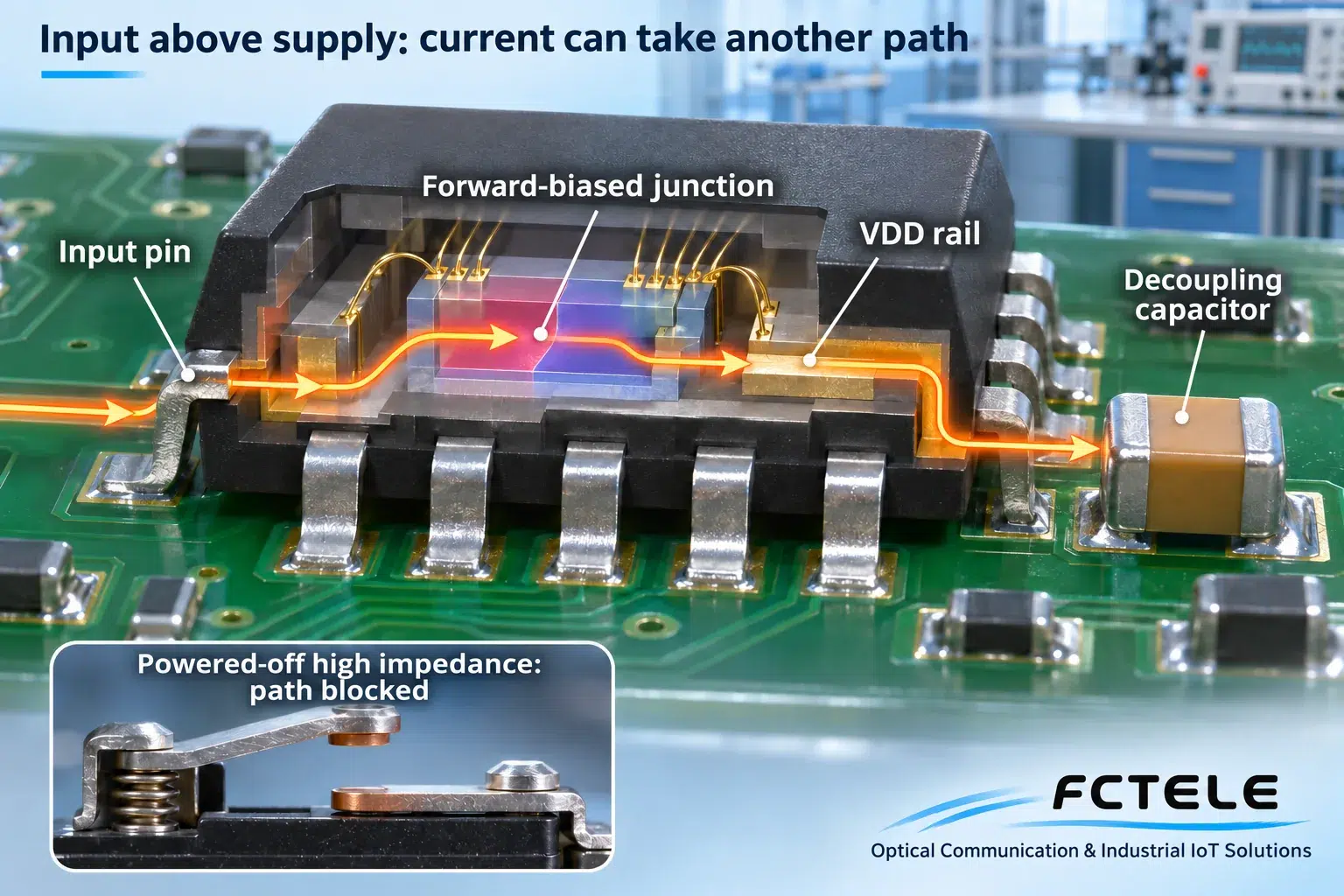
A voltage does not prove normal operation
Partial power may produce a dim indicator or some logic activity without satisfying normal voltage and current requirements. Reset, clock and separate power domains may be in inconsistent states. Activity on one pin therefore does not establish that the processor has booted, or that the communicating systems have valid data.
Verify the main supply, local rail, reset state and business data separately. A link indicator alone can turn evidence of local energy into a mistaken judgment of system health. Back-powering is also different from latch-up, which concerns a different sustained-conduction mechanism in parasitic structures. Damage or post-recovery malfunction must be assessed against component conditions and actual evidence, rather than inferred from the name of the symptom.
What powered-off high impedance guarantees
Two questions matter: can the external signal raise the supply rail through an unintended path, and does the device maintain its specified high impedance between signal input and output when powered down? High impedance means a small current under stated conditions. It does not mean absolutely zero current or galvanic separation. Specifications may use Ioff or powered-off leakage; read them together with the zero-supply condition, input voltage, temperature and applicable pins.
Disabling an output is not automatically equivalent to powered-off protection. An output can be tri-stated while an input-to-supply protection path remains. Some guarantees apply only to selected pins. Assess the named pins and supply combinations; labels such as high impedance, voltage tolerance or ESD protection do not establish complete hot-plug capability. Hot plugging also involves surge current, contact order, ground potential and communication state.
Design options include verified powered-off-protected interfaces, coordinated supply sequencing or disabling signal drivers as required. A series resistor may limit current but also changes edges and timing; an arbitrary resistance is not a universal repair. With an isolated interface, check both-side supplies and its powered-off default behavior. Signal-path high impedance must not be described as an insulation certification.
Check the complete communication system
First establish the boundary between a complete external port and the board-level circuit. Feichang serial-server documentation can establish the equipment category and connection requirements. The presence of a serial port does not establish that its interior contains the clamp path illustrated here, or that it inherits another IC’s powered-off protection. RS232, RS485 and USB have different electrical conditions; check the actual model documentation and power instructions separately.
During authorized maintenance or on a controlled bench, record which supplies are off and which signal sources remain active. Observe the target rail and input at suitable test points after confirming allowed voltage and measurement methods. Maintain the specified reference connection, and do not use resistance or continuity ranges on energized circuits. Changing one potential energy source at a time can help locate the source; do not blindly unplug production wiring or inject test voltage into an unknown terminal.
The final record should include the supply combination, interface connections, input state, rail changes, reset behavior and data recovery. After correction, repeat the same conditions and confirm powered-off leakage, startup sequence and data integrity against the documentation. This turns “the residual voltage disappeared when the cable was removed” into a traceable assessment of the current path, without treating a conceptual drawing as a diagnosis of a specific device.
Sources and scope
TI SCDA015 — Powered-off protection · TI — Logic gates and switches with Ioff · Feichang serial-server reference (Chinese)
Component references establish general mechanisms, not the component selection in a Feichang product. Actual wiring, voltage, leakage and sequencing require model-specific documentation.
Translated from the Chinese technical article: Read the original Chinese article.
Common questions
Does residual rail voltage prove back-powering?
No. Exclude stored charge, USB and other supplies, then observe whether removing and restoring the input changes the rail while the main supply state stays unchanged.
Is a tri-stated output equivalent to powered-off protection?
Not necessarily. An input-to-rail protection path may remain. Check Ioff or leakage for the specified pins and supply combinations.
Can internal logic levels be used as external serial wiring instructions?
No. External RS232, RS485 and board-level UART have different electrical conditions. Check the actual interface, level conversion and isolation documentation.
Further reading
UART receive FIFO overrun · RTS/CTS feedback and in-flight characters
