


ETHERNET / BASELINE WANDER
Why can the received reference move?
Ethernet magnetics have finite low-frequency response. A pattern-dependent slow component can be attenuated, shifting received levels and tilting a plateau. PHY baseline tracking can estimate and correct that offset within the applicable operating range. Droop alone does not establish a failed transformer. Verification must distinguish analog waveforms, recovered frames and application results.
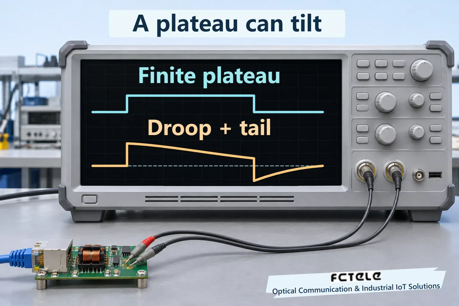
01 · A plateau tilts
A finite-bandwidth, AC-coupled channel attenuates slow components. A finite plateau can droop and leave an opposite-polarity tail.
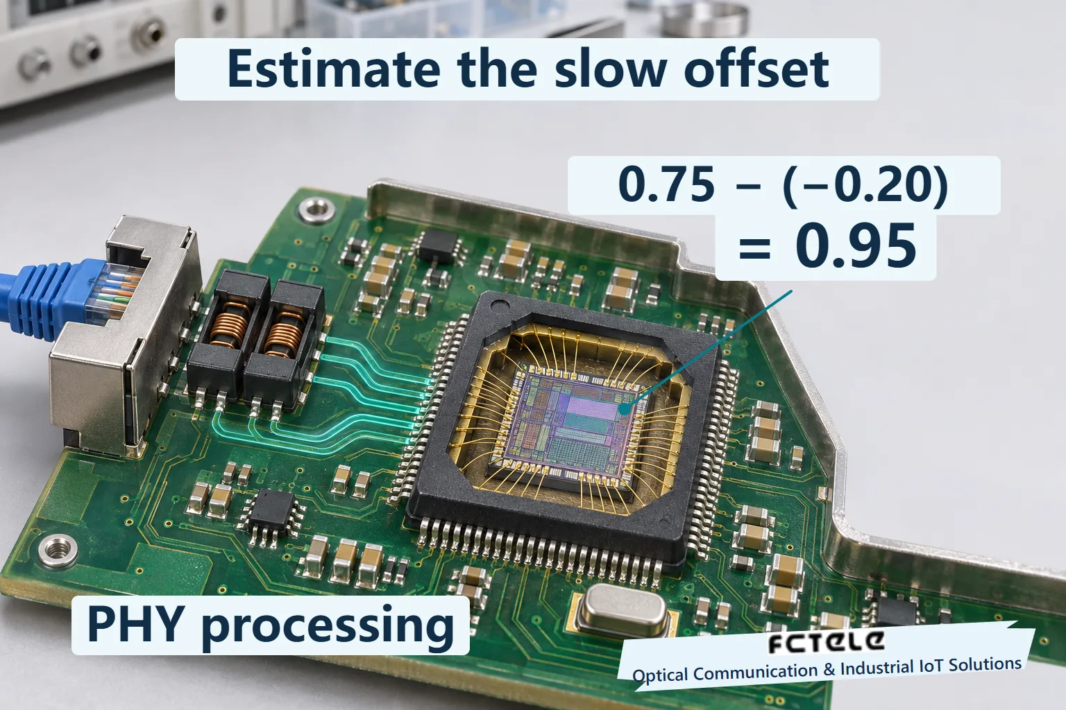
02 · A sample shifts
In arbitrary units, 0.75 minus an estimated offset of −0.20 gives 0.95. The intended value is 1.00; residual error remains.
03 · Two observations differ
An analog observation concerns line shape. A packet capture sees recovered frames and cannot directly reveal the internal baseline estimate.
Define the point
Record line side, coupling mode, reference and probe loading before comparing shapes.
Use valid conditions
Use the prescribed speed, patterns and instrument setup; the teaching plateau is not a conformance test.
Verify the application
Correlate port errors and complete transactions; retain uncertainty about unmeasured internal processing.
Selection and verification checklist — expand
| Check | What to confirm | How to verify |
|---|---|---|
| Interface | Actual speed and model | Equipment documentation and negotiated state |
| Waveform | Reference and probe conditions | Defined differential observation on a controlled bench |
| Outcome | Continuous valid data | Aligned port statistics and send/receive records |
Data on a network cable is not a succession of perfect rectangular pulses. As an industrial switch receives the line signal through connectors, magnetics and cable, both amplitude and shape can change. One change is easy to overlook: when a level remains in one direction for a relatively long interval, its received plateau moves toward the reference and can be followed by an opposite-polarity tail. Baseline wander concerns a slowly changing offset relevant to signal decisions; it does not establish that the equipment supply is dropping. Understanding it connects copper-port low-frequency response with decisions inside the PHY.
Start at the right observation point
A PHY, or physical-layer transceiver, turns digital information into line signals and recovers it at the receiving end. A common copper Ethernet interface uses signal transformers between the PHY and cable. Magnetic coupling transfers changes while the two windings have no direct conducting connection. The question here goes beyond isolation: why can an initially flat interval change shape after passing through the channel?
Separate three locations: the intended transmitted line level, the level arriving at the receiver’s analog input after the channel, and the digital data delivered after PHY processing. These should not be drawn as one identical trace. An ordinary packet capture generally sees frames that have already been recovered. It cannot directly display the voltage plateau after a transformer. Correct packets at a mirror port do not establish that the analog signal needed no correction.
“Relatively long” also needs a reference to the system response time. This explanation does not turn consecutive zero bits in an application message directly into a constant low line level. Ethernet applies the relevant encoding and scrambling; application bytes are not copied unchanged into line symbols. The plateau magnifies a low-frequency response mechanism and is not a complete Ethernet test pattern ready to transmit.
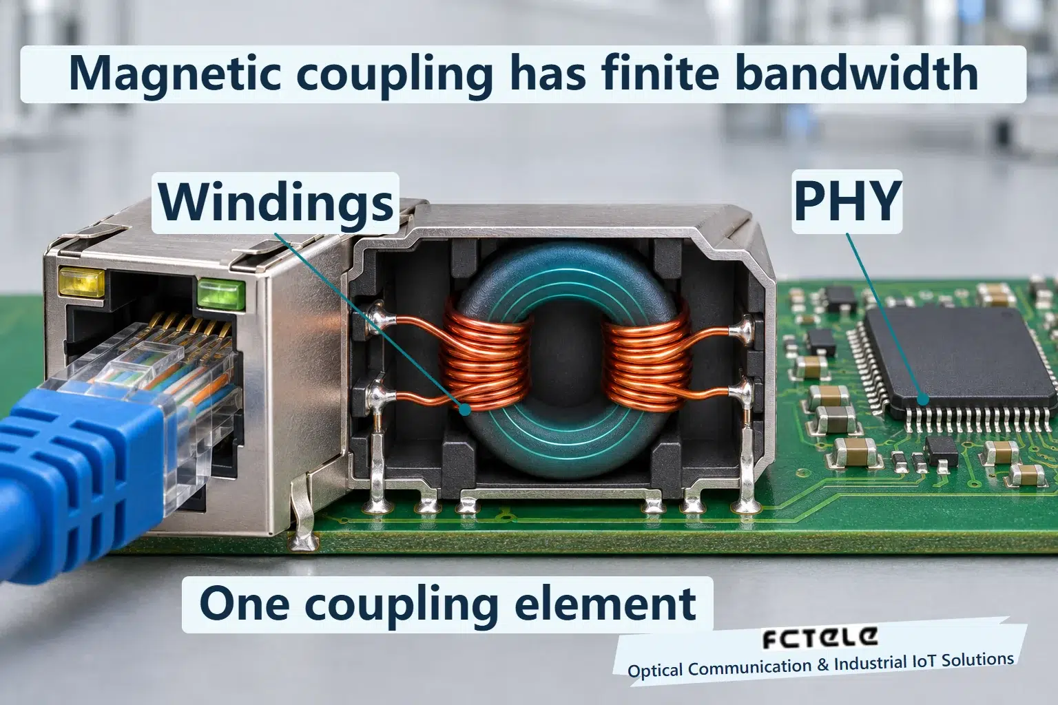
How finite magnetizing inductance tilts a plateau
A real transformer is not an ideal copier with unlimited bandwidth. For its low-frequency behavior, magnetizing inductance is an equivalent parameter describing the current required to establish magnetic flux. Maintaining voltage across an inductance changes the associated current over time. Together with source and load impedances, the channel cannot preserve a constant offset indefinitely. Low-frequency and DC components are attenuated.
Consider a simplified teaching experiment: apply a positive plateau of finite duration to an AC-coupled channel. The arriving leading edge raises the output. While the input stays unchanged, the output gradually moves toward its zero reference. When the plateau ends, the falling edge produces an opposite change. The output can first move below zero and then return toward the reference. Real magnetics at both ends and the cable need not follow a single time constant, but this process explains a tilted received plateau.
Do not automatically call this core saturation. Finite low-frequency response can produce droop under linear, small-signal conditions. Saturation is a separate condition that can introduce substantial nonlinearity and requires its own evidence. Droop alone does not establish a failed component either. Components have specified operating conditions, and transceiver design must accommodate channel distortion within the applicable limits.
Separate amplitude attenuation from plateau droop. Uniform scaling reduces the entire waveform by the same proportion while retaining its relative shape. Droop changes the height within one plateau and includes history left by earlier signal intervals. Both can coexist. Comparing only a peak misses the change within the plateau; one DC reading also cannot describe this dynamic response.
How droop affects a symbol decision
A receiver samples at appropriate times and uses level positions to decide line symbols. When a signal favors one direction over an interval, the channel attenuates its slowly varying component. Subsequent symbols can then be displaced relative to the original reference. Plateau droop is an easily drawn local manifestation; the pattern-dependent low-frequency offset is what baseline tracking must follow.
Walk through an example in arbitrary units. Suppose the intended sample for a symbol is +1.00. At this instant, assume the channel introduces a slowly varying offset of −0.25 and ignore other distortion. The received sample is therefore +0.75. If processing estimates the offset as −0.20, subtracting that estimate from the sample gives +0.95, leaving a residual of −0.05. Subtracting a negative quantity increases the result. “Correction” should not always be drawn as subtracting another positive value.
These numbers explain the relationship between a symbol and an offset. They are not port voltages, decision thresholds or product specifications. Real receivers must also handle noise, amplitude variation and intersymbol effects. One sample cannot predict a bit error rate. Inaccurate estimation, inputs outside the operating range or excessive other distortion can degrade recovery. A correction function does not permit arbitrary combinations of magnetics and cabling.
Keep the reference consistent in the calculation. All signs here refer to the same teaching zero, not the voltage of one conductor against chassis ground. Both conductors moving together is a common-mode issue, distinct from a slow offset in their difference. Subtracting numbers from different observation points or references cannot demonstrate effective correction, even when the arithmetic is correct.
The PHY tracks an offset; it does not retransmit for software
Public PHY documentation describes baseline-wander correction. Some implementations pass samples to digital signal processing to track and correct the slow offset. Other devices may divide the work between analog and digital paths. The illustration shows a functional relationship. It does not require every PHY to contain the same standalone block, or imply that a Feichang product uses a chip from the references.
Other receiver functions have different tasks. Gain control puts the signal in a suitable processing range. Equalization addresses channel-induced shape distortion. Baseline tracking addresses a slow offset, and clock recovery finds useful sampling times. Implementations coordinate these functions. All operate during physical signal recovery; none replaces frame checking, application confirmation, packet retransmission or network redundancy.
Encoding and scrambling help organize a transmittable signal, but “scrambled” does not mean every observation interval is exactly balanced between positive and negative levels. Design and conformance verification must account for unfavorable patterns and component conditions. Different speeds also use different line representations. One teaching plateau is not a universal copper-port waveform or test limit.
Turn the explanation into reproducible verification
If errors increase under a particular workload, first record negotiated speed, error-count increments, supply conditions and port events. Then compare a known-good link under the same configuration. Message length, content, interference, cable termination and supply changes can all affect symptoms. Correlation alone does not identify baseline wander. Establishing an analog cause requires a controlled bench suitable for the speed, prescribed patterns, defined observation points and appropriate instruments.
Differential probing, bandwidth, termination load and the instrument’s own AC-coupling setting can change apparent droop. State which side was observed, the coupling mode and how the reference was defined. Do not attribute probe-induced distortion to an internal product fault. Without those measurement conditions, report the available port statistics and application comparisons, retaining the internal mechanism as an unverified hypothesis.
The Feichang managed DIN-rail industrial switch with four 10G optical and eight Gigabit copper ports lists 10/100/1000BASE-T adaptive RJ45 interfaces on its official product page. It provides a real industrial copper-port context. Exact magnetics, PHY implementation and accessible diagnostics still require the relevant model documentation. Retain evidence of both physical-channel conditions and end-to-end operation. Bringing the baseline back to a useful decision reference is one part of data recovery. Continuous correct application communication ultimately needs actual send-and-receive records.
Sources and scope
Analog Devices ADIN1300 — receive functions · Microchip LAN8720A — §3.1.2.2 · IEEE 802.3at 350µH Ad Hoc, 2007 — historical engineering discussion · Feichang industrial switch (Chinese)
Chip documentation explains general mechanisms and does not establish use in a Feichang product. The historical discussion is not a current product test limit. No model thresholds or wiring instructions are supplied.
Translated from the Chinese technical article: Read the original Chinese article.
Common questions
Does droop establish a failed transformer?
No. Finite low-frequency response produces droop even in linear operation. Assess it using specified conditions and limits.
Are consecutive zero application bytes a constant low line level?
No. Encoding and scrambling intervene. The teaching plateau explains response, not a complete test pattern.
Can a packet capture directly show baseline wander?
Generally no. A capture sees recovered frames. Verifying the analog mechanism needs suitable instruments and defined observation conditions.
Further reading
Gigabit copper echo cancellation · Ethernet magnetics and isolation
