

AUDIO / SIGNALS AND TRANSPORT
Does the same connector mean the same audio signal?
No. Identify the representation, transport and timing separately. AES/EBU commonly means AES3; AES50 is a dedicated multichannel synchronous link; AES67 is IP audio interoperability. Converting between these families requires the appropriate signal processing or gateway, not just a passive cable. Verify endpoint formats and model-specific capabilities before choosing a fiber extension.
01 · Voltage and samples
An analog line carries voltage. ADC sampling is a separate conversion stage, not a property of its connector.
02 · Serial and dedicated links
AES3 alternates A/B samples in one direction. AES50 carries multiple channels and a parallel timing reference.
03 · Packets and time
AES67 sends RTP packets through an IP network. PTP reference time and buffering support continuous sample delivery.
Identify the signal
Read the port label and documentation; XLR and RJ45 shapes alone are insufficient.
Plan the reference
Check clock source and follower roles, or the matching PTP and stream settings.
Verify each channel
Send distinct test content, then check routing, levels, synchronization and recovery.
Selection and verification checklist — expand
| Check | What to confirm | How to verify |
|---|---|---|
| Interface | Analog, AES3, AES50 or AES67 | Exact endpoint documentation and signal mode |
| Timing | Reference and follower relationship | Lock/PTP state and sustained operation |
| Outcome | Every channel, direction and recovery | Distinct known test signals and documented reconnection tests |
AES/EBU is the common name for the AES3 professional digital audio interface; they should not be presented as competing formats. Analog audio carries a continuously varying voltage, AES3 normally carries two channels of digital samples, and AES50 carries multiple channels with synchronization over a dedicated bidirectional link. AES67 instead sends samples in IP packets and uses PTP timing and a receive buffer to reconstruct continuous playback. Matching connectors do not establish signal compatibility.
1. Separate the signal, the interface and the connector
Analog and digital describe how sound is represented. AES3 and AES50 describe how samples are organized, synchronized and transported. XLR and RJ45 describe connector shapes. PCM, or pulse-code modulation, represents amplitude using numerical samples taken at regular intervals; it is not itself a cable you can plug in. MP3 and AAC are compression codecs, not interfaces at the same level as AES3.
AES standards are developed by the Audio Engineering Society; EBU stands for the European Broadcasting Union. In practice, an “AES/EBU port” usually means the AES3 professional interface, particularly its 110-ohm balanced XLR implementation. Still verify the physical implementation, sample mode and channel status. That common name does not mean every interface marked AES is identical. The first table compares the four principal link families.
| Comparison | Line-level analog audio | AES/EBU (AES3) | AES50 | AES67: IP audio interoperability |
|---|---|---|---|---|
| What travels on the link? | Continuously varying voltage representing sound. | A serial stream containing preambles, audio samples and status bits. | Framed multichannel audio, with audio clock signals carried in parallel. | PCM samples in RTP/UDP/IP packets; PTP messages establish a common time reference. |
| Channels per connection | Normally one channel per balanced line; two signal conductors are not two channels. | A and B in the common two-channel PCM mode, in one direction. | Multiple channels in both directions; available count depends on sample mode and endpoints. | Multiple channels grouped into streams; stream and device limits depend on format, packet time and endpoint capability. |
| Common connector / medium | XLR or TRS for balanced lines; RCA for some unbalanced connections. | Commonly 110-ohm balanced digital cable with XLR; AES3id also provides a 75-ohm coaxial implementation. | Often RJ45 or ruggedized connectors with Cat5 or better cable; follow equipment shielding requirements. | Copper or fiber Ethernet through a suitably designed switched network. |
| Before transmission | Microphone preamplification or line driving; this section remains analog. | PCM samples → subframe construction → line coding → electrical driver. | Per-channel ADC or digital source → sample organization → dedicated link transmitter. | PCM sample grouping → RTP header → UDP/IP and Ethernet transmission. |
| At the receiver | Differential reception; filtering and ADC sampling if digital processing is needed. | Line decisions → timing recovery → preamble detection → A/B sample extraction. | Receive data and synchronization reference → channel distribution → DSP or DAC. | Receive packets → check sequence and stream format → buffer → deliver samples at the synchronized rate. |
| Where does timing come from? | No digital sampling clock on the analog line itself; ADCs and DACs require clocks. | Interface timing is recovered from stream transitions; system synchronization must still be planned. | Audio clock travels in parallel with data, following the configured synchronization hierarchy. | PTPv2 provides reference time; the media sampling clock and RTP timestamps are related to it. Playback does not follow packet arrival intervals. |
| Can an ordinary Ethernet switch forward it? | No: this is not Ethernet data. | No: AES3 is not Ethernet data. | Not as ordinary Ethernet/IP traffic; use matching AES50 equipment. | Switched Ethernet can carry it, provided bandwidth, QoS, multicast and PTP are correctly engineered. |
| Faults and useful evidence | Noise, imbalance and clipping: check levels and differential input conditions. | Loss of lock, silence or clicks: check sample rate, status, cable and lock indication. | Link up but wrong channels or timing: check clock source, routing and mode. | Lost/late packets, synchronization or subscription faults: check packet statistics, buffer, clock and SDP separately. |
| Conversion to another family | Analog-to-digital requires an ADC and a transmitter for the target interface. | Analog output needs an AES3 receiver and DAC; other formats need an appropriate bridge. | AES3, Dante or other systems need a converter explicitly supporting both sides. | AES50/AES3 require a suitable gateway; Dante interoperability requires supported and matching AES67 modes. |
2. Analog audio: receive a voltage difference before digitizing
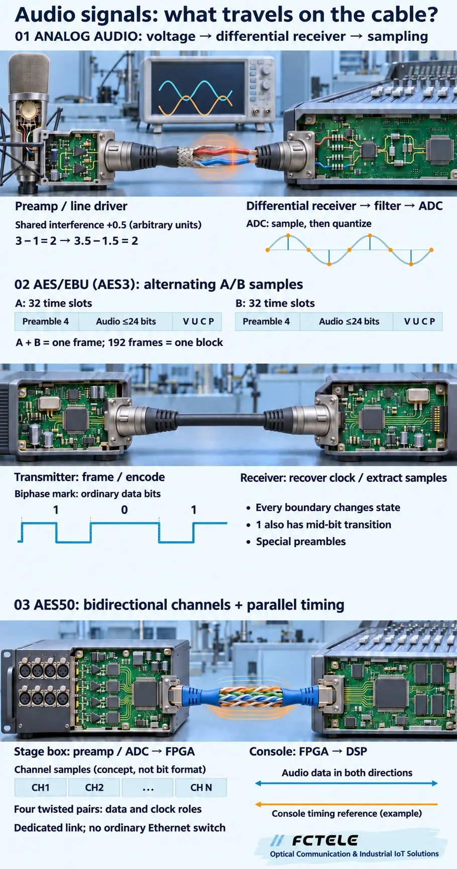
A microphone turns changing sound pressure into a small electrical signal. A suitable preamplifier brings it into a usable range. On the line-level analog section, the receiver sees a continuously varying voltage, not a binary audio file. When that line feeds a digital mixer, the voltage passes through the receiver and anti-aliasing filter before an ADC, or analog-to-digital converter, samples and quantizes it.
A balanced connection relies on matching the two conductors’ impedances to their surroundings; the receiver primarily responds to the voltage difference. Some outputs drive opposite-polarity signals, but that is not the only balanced-output arrangement. In arbitrary teaching units, conductors at 3 and 1 have a difference of 2. If shared interference raises both by 0.5, 3.5 minus 1.5 is still 2. Real common-mode rejection and input range are finite, and unequal interference leaves an error. The shield is not a second audio channel.
Sample rate is the number of samples taken each second; bit depth describes how finely sample amplitudes are represented. Neither is the number of channels in an analog cable. Anti-aliasing filtering limits high-frequency input before sampling. Once a preamp or ADC input clips, changing the downstream digital cable or adding fiber cannot restore the missing waveform. Check phantom power, microphone level, line level and loudspeaker power output separately.
3. AES3: put two channels into one serial stream
Assume left and right channels have already become 48 kHz, 24-bit PCM samples. In each sample period the transmitter takes one A-channel sample and one B-channel sample and sends two successive subframes. Each subframe has 32 time slots: four for the preamble, up to 24 for audio, then one each for V, U, C and P. Two subframes make a frame; 192 frames make a block over which channel-status information is accumulated.
V indicates sample validity, U carries user data, C contributes channel status, and P provides parity across the specified part of a subframe. Line coding does not use a high voltage to mean loud sound. Ordinary data bits use biphase-mark coding: every bit boundary has a transition, and a 1 has another transition in the middle. Preambles use special patterns identifying subframe and block boundaries, so ordinary-bit rules cannot simply be imposed on them.
The receiver detects line transitions, recovers interface timing using processes such as a phase-locked loop, identifies preambles, checks status and extracts samples. A DAC, or digital-to-analog converter, and reconstruction filter are needed only when analog output is required. This is why AES3 receivers commonly show LOCK, while an analog line has no equivalent coded-stream lock state. At 48 kHz, 48,000 frames per second multiplied by 64 slots per frame gives 3.072 Mbit/s of slot rate. This is neither acoustic frequency nor a claim that all transition counts equal that number.
4. AES50: multichannel samples travel with a common reference
A stage box can preamplify and digitize multiple microphones, arrange their samples into link data and send them to a console. Return audio travels in the other logical direction over the same physical cable. AES50 uses 100BASE-TX physical-layer technology to carry framed audio and uses available cable pairs to carry audio clock signals in parallel. Borrowing Ethernet physical-layer technology does not mean an ordinary Ethernet switch can forward the link.
A field-programmable gate array (FPGA) can organize link samples; digital signal processing (DSP) then works on the received audio. These functional roles do not specify a particular product circuit. The synchronization problem is that endpoints must process samples at compatible rates. Two freely running clocks labelled 48 kHz can still differ slightly; a receive buffer gradually fills or empties, potentially leading to dropped or repeated samples or loss of lock. Establish a reference source and follower relationship rather than setting every device to its internal clock. The illustration uses the console as reference only as an example; actual roles follow the equipment configuration.
Socket count is not channel count. The current Chinese product information for the FCTEL FCP-1700-EF series specifies 48 channels in each direction per AES50 link at 44.1/48 kHz, or 24 at 96 kHz. EF1 through EF4 refer to one through four AES50 links, not one through four audio channels. Those are series-specific specifications; do not assume every AES50 device exposes identical channels, control or redundancy functions.
5. AES67: turn network packets back into continuous audio
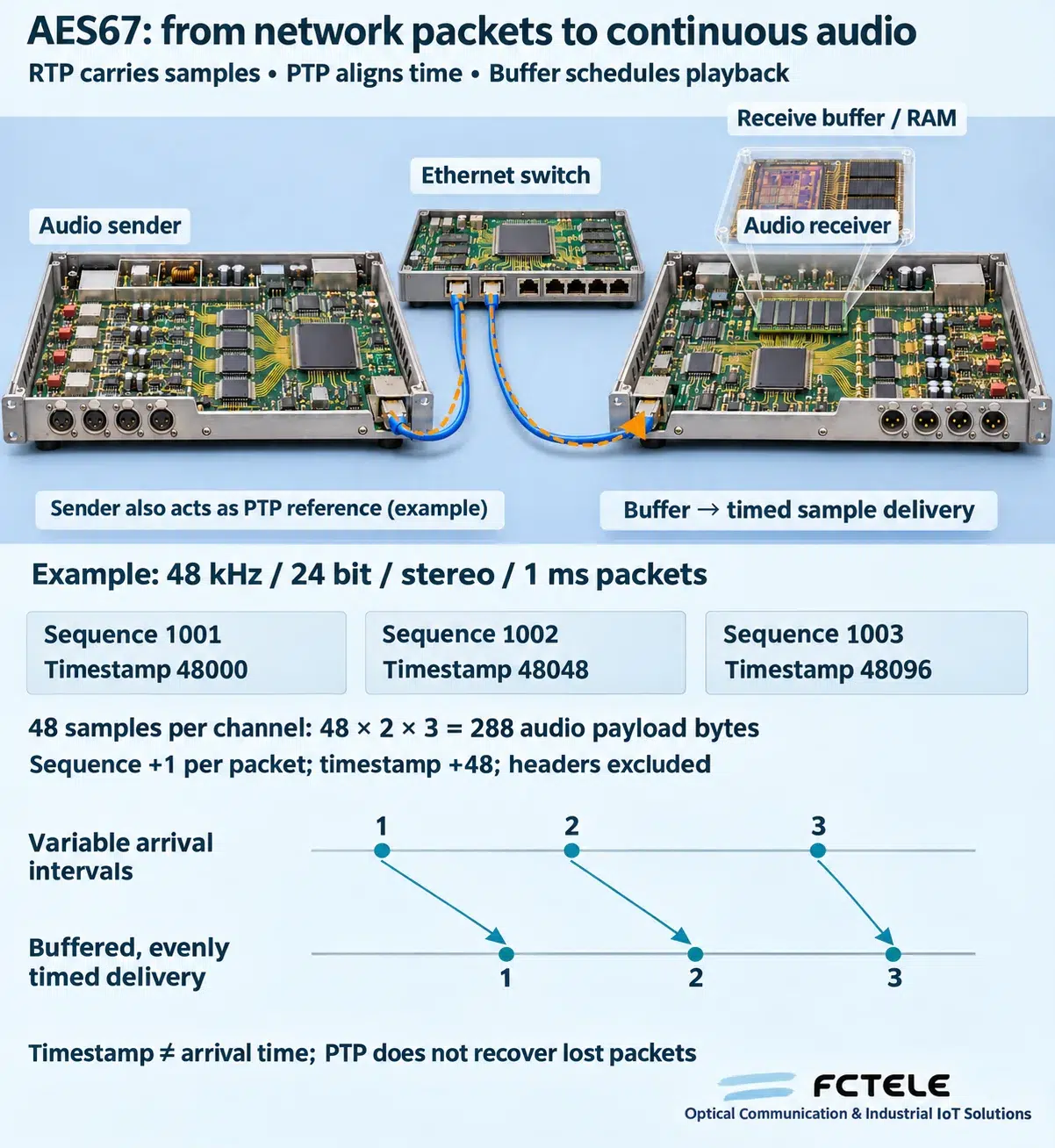
AES67 specifies interoperability conditions for real-time audio over IP. A sender packages PCM samples into RTP, the Real-time Transport Protocol, and sends them using UDP/IP over Ethernet. What reaches the receiver is a sequence of packets, not a voltage ready for a loudspeaker. Unlike an AES50 dedicated point-to-point link, AES67 audio can traverse a suitably configured switched network. AES67 is not an entire discovery and control system in which all equipment automatically recognizes everything else; connection management still needs a suitable arrangement.
Consider one compatible operating example: 48 kHz, 24-bit stereo with 1 ms of audio in each packet. Each channel contributes 48 samples; interleaved across two channels, the payload is 48 × 2 × 3 = 288 bytes, before RTP, UDP, IP and Ethernet overhead. For sequence numbers 1001, 1002 and 1003, choose a starting sample timestamp of 48000: the next timestamps are 48048 and 48096. The sequence increases by one per packet and the timestamp by 48. It locates samples on the media timeline, not the instant a packet reached the computer. Starting values are illustrative; 1 ms is not the total end-to-end delay.
PTP, the Precision Time Protocol, exchanges messages to establish a common time reference. Endpoints use it to maintain compatible audio sampling rates and relate RTP media time to reference time as specified. PTP messages and audio packets have different jobs: synchronization does not carry the samples or automatically replace lost packets. An RTP timestamp is not directly a PTP wall-clock time expressed as hours and minutes.
Switch queues make packet arrival intervals vary. The receiver buffers samples and reads them at the agreed playback time and synchronized rate, rather than playing each packet immediately on arrival. Buffering absorbs arrival jitter within its design allowance and adds waiting time. A packet that misses its playback deadline, or never arrives, can still cause missing audio. Sequence numbers help identify gaps and reordering; RTP itself guarantees neither retransmission, correction nor timely delivery. Diagnose PTP synchronization and network congestion separately.
Before connecting, match the SDP, or Session Description Protocol, parameters: destination address and port, encoding, sample rate, channel count, packet time and timing relationship. Then check multicast planning, quality-of-service priorities, bandwidth and PTP state. Dante can interoperate with other ecosystems only when the relevant hardware, firmware and configuration support a matching AES67 mode. Native audio between Dante devices still uses Dante transport even with AES67 enabled. SMPTE ST 2110-30 builds on AES67 with additional broadcast constraints; configurations are not universally interchangeable.
For a FCTEL media converter or industrial switch, forwarding Ethernet frames covers only part of the network path. It does not prove the product includes an AES67 encoder, subscription management or dedicated PTP functions. Verify each model’s actual networking capabilities and commission endpoints, switches and clocking as a system. An AES50-specific fiber extender is not automatically an AES67 conversion gateway.
6. Where do other digital audio interfaces fit?
Professional and consumer equipment uses many other digital audio interfaces. The second table covers common external wired interfaces and network families, and includes the common board-level interface I²S. It is a practical connection guide, not an exhaustive list of every historical standard. Wireless systems such as Bluetooth also involve wireless protocols and codec negotiation and cannot be specified using a wired-interface table alone. Channel figures are common examples only under the conditions shown.
Serial links, USB host connections and switched networks organize audio differently. Network audio packetizes a group of samples, then relies on synchronization and receive buffering for timed playback. An Ethernet link light confirms a lower-layer connection, not correct timing, subscription or channel mapping. Dante and non-Dante devices using AES67 still need supported modes, stream formats and synchronization parameters on both sides.
| Interface / family | Transport and common channel examples | Timing and connection | Frequent misconception |
|---|---|---|---|
| S/PDIF (consumer IEC 60958) | Coaxial RCA or TOSLINK optical; linear PCM is normally stereo, with some supported compressed streams. | Receiver recovers timing from a point-to-point stream. | Related to AES3, but electrical and status conventions differ. A connector adapter does not guarantee compatibility. |
| ADAT Optical | Optical multichannel link: commonly eight channels at 44.1/48 kHz, or four at 96 kHz when S/MUX is supported. | Timing comes from the optical stream or a configured external reference. | The socket may resemble optical S/PDIF, but coding differs. Set the correct port mode. |
| MADI (AES10) | Serial multichannel audio over coax or fiber; 56/64-channel modes are common at 48 kHz. | Clock recovered from the link; input and output are commonly connected separately. | Fiber does not turn this serial interface into switched Ethernet. |
| USB Audio | USB streams between a host and an audio device; channels depend on device and mode. | USB scheduling and audio clocks work together; asynchronous devices can feed back their rate. | Two ordinary USB sound interfaces generally cannot connect directly without the necessary host role and system support. |
| HDMI / DisplayPort audio | Audio accompanies an audiovisual link; may carry multichannel PCM or supported encoded formats. | Link timing and receiver capability negotiation; not a professional XLR audio interface. | ARC/eARC are separately conditioned HDMI return functions. Check ordinary input/output direction as well. |
| Dante | Ethernet/IP audio with subscriptions between devices and channels. | Network clock synchronization, buffering and routing work together; the switched network must meet design requirements. | Dante is an ecosystem. AES67 support must be checked on the particular device, not inferred from its Ethernet socket. |
| AES67 / SMPTE ST 2110-30 | Standards for interoperability using RTP audio streams; channel count depends on stream and endpoint configuration. | PTP timing, network transport and receive buffering. | AES67 is not an upgraded AES50 or all of Dante. Both sides must agree on compatible operating parameters. |
| AVB / Milan | Real-time Ethernet media; Milan constrains AVB audio interoperability. | Network timing and traffic management require appropriate endpoints and supported switches. | An ordinary switch, or an endpoint merely labelled AVB, does not by itself ensure Milan interoperability. |
| I²S (board-level) | PCM between chips, with separate data, bit clock and word/left-right clock functions. | A short-distance synchronous board interface, not a field-cabling interface. | I²S is not I²C. Its pins cannot connect directly to AES3, AES50 or Ethernet. |
7. Use the same stereo program to check conversion and fiber extension
To send a left/right program, line-level analog normally needs two balanced connections. A common two-channel AES3 link carries the A/B samples over one digital connection. AES50 maps left and right into two agreed channels while its other channels may carry other programs. These arrangements represent the same program, but a passive adapter cannot automatically exchange them. Analog-to-digital conversion needs an ADC, digital-to-analog needs a DAC, and conversion between digital formats requires appropriate receiving, transmission, mapping and, where necessary, sample-rate conversion.
Fiber extension changes the transmission medium, not automatically the interface protocol. The Chinese FCTEL product pages list analog/AES digital configurations for FCA-AD8, AES/EBU for FCA-AES8, and AES50 services for FCA-053710 and the FCP-1700-EF series. Verify the ordered version. An ordinary Ethernet media converter cannot be treated as an AES50 extender just because both have RJ45 sockets. Even with dedicated equipment, commission sample rate, clock source, channel directions and mapping together.
During acceptance, send distinct known content through one channel at a time and verify the far-end number and direction. Then check analog levels or digital lock and error status. Run continuously in the intended sample mode and verify disconnection and recovery behavior according to the equipment instructions. Hearing one piece of audio proves only part of the path; it does not replace checks across every channel, the clock system and recovery.
Common questions
Are AES/EBU and AES3 two different digital audio formats?
Usually no. AES/EBU is the common name for the AES3 professional interface, particularly its balanced XLR implementation. Check the physical version and sample mode. AES50 is a different multichannel synchronous interconnection standard.
Can an adapter interchange analog XLR, AES3 XLR and AES50 Ethernet-style connectors?
Connector shape is insufficient. Analog/digital conversion needs ADC/DAC and the appropriate interface; AES3/AES50 conversion needs equipment supporting both protocols and channel mapping. An ordinary passive adapter does not perform that processing.
Why can the link and clock be locked while the audio is still wrong?
Lock does not prove correct channel mapping, sample mode, validity or program content. Check direction, routing and output processing one channel at a time. Network audio additionally needs correct subscriptions, stream parameters and time synchronization.
Can AES67, AES50 and Dante interoperate directly?
Not merely because they use similar Ethernet-style sockets. AES50 is a dedicated synchronous link and needs an appropriate gateway to AES67. Dante/AES67 interoperability requires supported, matching stream formats, packet times and synchronization settings; discovery, control and redundancy features do not automatically interoperate.
Sources and related products
Key references: AES3 · AES50 · AES67 · Dante interoperability
All references (13) — expand
- EBU Tech 3250: AES/EBU interface, subframes and coding
- TI SRC4382: digital audio receiver/transmitter, PLL and serial ports
- AES project status: AES50 scope and synchronization
- RME ADI-648: ADAT, S/MUX and MADI modes
- USB-IF: USB Audio device class specification
- Audinate: Dante and AES67 interoperability
- HDMI: ARC/eARC audio return
- VESA: DisplayPort audiovisual transport
- Milan: endpoints, AVB switches and interoperability
- IETF RFC 3550: RTP sequence, timestamps and transport limits
- AIMS: PTP, media clocks and alignment in AES67/ST 2110
- Merging: AES67 stream and SDP configuration examples
- Audinate: AES67/ST 2110-30 modes and interoperability limits
Analog / AES3: FCA-AD8 · FCA-AES8
AES50: FCA-053710 · FCP-1700-EF series
Product sources above are in Chinese. Interfaces, channels and fiber configuration depend on the exact model and ordered version.
Further reading: TOSLINK, coaxial, RCA and XLR interfaces · Audio fiber applications and interface limits.
English edition of the original Chinese technical article. Illustrations explain generic mechanisms with AI assistance; they are not photographs of a specified product circuit or field measurements.
