


The key to wiring a 16-channel contact-over-fiber unit is the input type, output form, channel direction, and rated conditions. First check the model’s terminal diagram, then test channel by channel; the fiber only transmits status, and both end devices and remote loads must be powered correctly. A single generic diagram cannot replace the wiring instructions for all products.
1. First, write down the 16-channel requirements clearly
For each channel, write down the signal name, sending location, receiving location, normal and alarm meanings, input form, and external load. A unidirectional 16-channel usually describes the channel capacity in one direction; bidirectional configurations are defined by the model, and you cannot assume both ends have 16 inputs plus 16 outputs at the same time.
The Feichang FCP-K16G product description offers up to 16 channels unidirectional or 8 channels bidirectional, supporting dry and wet contact types. When ordering, confirm the specific combination, the role of each end, and the terminal definitions. Dual optical path backup is transmission path redundancy; it does not mean the same set of terminals can be split into two independent control systems.
Keep numbers and labels for spare channels, and record the grouping of common terminals. If different voltage or power systems need to connect to the same device, first check the isolation and common terminal conditions; you cannot directly short the reference wires of multiple systems just because they are all called common terminals.
2. How does a dry contact input form a detection loop?
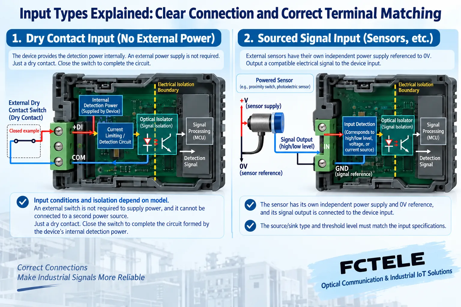
A dry contact itself does not actively provide voltage; a mechanical switch or relay contact is only responsible for on and off. A suitable input detection circuit will recognize this change under its allowed conditions. After the external contact closes, the detection loop is established and the device determines the corresponding state; after it opens, the loop changes and the device determines the other state.
The actual detection voltage, current, and terminal numbers are defined by the product. The diagram only shows a general relationship and does not give a fixed voltage applicable to all versions. Do not inject extra voltage into an input that only allows dry contacts, and do not confuse the action meaning of the contact with normally open and normally closed wiring.
When using a normally closed contact, both the normal closed loop and a broken wire will affect the receiving state, and the receiving system must interpret it according to the plan. If you need to clearly distinguish contact action from line breakage, also confirm whether dedicated line supervision is available; ordinary two-state transmission cannot automatically add a third ‘broken wire’ judgment.
3. A wet contact is not any powered output
A powered input must meet the allowed level, polarity, reference terminal, and input current conditions. When a sensor uses a source or sink output, the current path is different and must match the input detection method. Just seeing that the sensor has three wires or a lit lamp does not prove the wiring is correct.
First check the signal source manual and the fiber optic transceiver input data, then draw the complete current loop. Wire colors are not a unified terminal definition across all manufacturers. If the level exceeds the range, the reference terminal is wrong, or different power systems are connected incorrectly, the input may not recognize the signal or may even be damaged.
If the product description introduces wet contacts together with optical MOS outputs, also distinguish input detection conditions from output device ratings. The voltage and current that the output can withstand cannot be directly used as the allowed input range. When the data is unclear, first confirm the delivered version; you cannot copy web values and piece together a wiring plan.
4. Look at relay output and load power separately
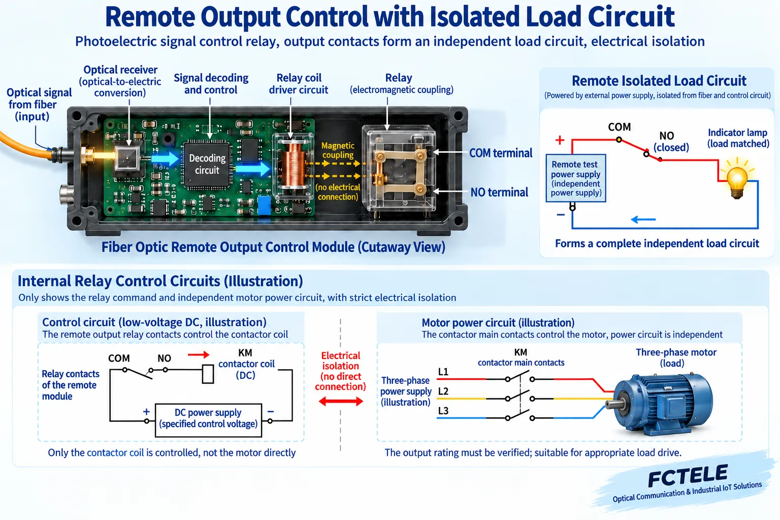
A passive contact output is equivalent to a remotely controlled switch. If a normally open contact controls a test indicator light, current should flow from the allowed remote power supply, through the contact and the light, and back to the other end of the power supply. Without an external power supply, the contact will not provide electrical energy to the light out of nowhere even if it closes.
Normally open, normally closed, and common contacts must be identified according to the terminal diagram; some outputs provide only one contact form. The relay coil drive and the contact load circuit are not the same circuit, and you cannot short all three terminals common, normally open, and normally closed together. Electronic outputs are also not necessarily equivalent to passive relay contacts; check polarity, voltage drop, and leakage.
The load’s starting current and switching surge also participate in selection. Solenoid valves, contactor coils, or lamps may have different transient conditions even if the steady-state current is not large. When the output capacity is exceeded, use appropriate intermediate drive; protection measures are determined by the load and control plan, and you cannot directly drive a high-power motor with communication terminals.
5. How to turn on channels one by one after power-up
After the actual execution circuit is isolated or placed in a controlled state, first confirm the power supply at both ends and the optical path. Give the first channel an allowed test state, observe local recognition, remote output, and the receiving system, then change the state to verify recovery. After confirming this channel, add the next channel and record whether it is inverted or misrouted.
Test multiple channels acting simultaneously and holding continuously, and check the common terminals, load power, and receiving system acquisition. Mechanical contact bounce may affect the input, and device filtering may also affect short pulses; when counting is needed, check the effective pulse width and operating frequency, and you cannot use ordinary state testing to replace pulse acceptance.
6. Fault states are also part of the wiring plan
For models that support preset outputs, clarify whether each channel should be open or closed when the optical path is not connected, and verify the actual effect. A broken fiber, device power loss, and input wire breakage are different conditions, and you cannot assume the outputs are exactly the same. A normal state appearing consistent does not mean the application meaning is correct when communication is lost.
When replacing the output load, also recheck whether the rated capacity applies to the new load nature. After a circuit originally connected to an indicator light is changed to a coil, the switching surge and action timing may both change. Maintenance personnel should not skip verification just because the old wiring once worked; instead, write the change into the channel table and retest the relevant conditions.
Ordinary digital signal remote transmission does not automatically become a safety control function. Emergency stop, dangerous actions, and personnel protection require corresponding safety designs, and you cannot obtain certified capability by setting a channel to normally closed. After maintenance, verify that all temporary test wires and configurations have been removed, and save the terminal diagram, channel table, interface conditions, and acceptance results so later personnel can continue to use them.
Sources:Feichang FCP-K16G product description;Feichang FCP-K1/2 product description;Feichang FCP-K4 product description;TI digital input module design data;OMRON relay usage precautions;IEC 61000-4-5 surge immunity test description. The schematic illustrations are general principle diagrams, belonging to general mechanism illustrations, not product photos, measured waveforms, or certification documents.
Translated from the Chinese technical article. Source first published: 2020-06-18. Source last revised: 2026-10-13T13:13:08+08:00. Read the Chinese source
