


Access, aggregation, and core describe a switch’s position and responsibilities in a network. They are not three fixed physical shapes, and they do not directly equal Layer 2 or Layer 3 devices. Access connects terminals, aggregation concentrates the paths of multiple access areas, and core connects important areas. A small network can merge roles. When choosing equipment, you should look at actual traffic, interfaces, and the impact of failures, rather than forcing a three-tier device architecture.
The access layer is closest to the actual devices
Cameras, controllers, computers, or wireless access points usually connect first to an access switch. It needs to meet the number of terminal interfaces, speed, power supply, and installation conditions. For terminals that support standard PoE, you also need to check power supply requirements separately; for fiber terminals, you need to confirm optical interface compatibility. You cannot decide all interface types based only on the number of devices.
The access layer also handles sending terminal traffic to the target location. If terminals mainly communicate within their own area, some traffic can stay in that area; if they need to access a remote server, it will pass through the uplink. The communication direction differs for each project. You cannot assume all data always flows from bottom to top, and you cannot understand access equipment as a power strip with no forwarding capability.
The aggregation layer concentrates the paths between areas
After multiple access switches connect to an aggregation node, the aggregation node becomes an important connection point between several areas. For example, if devices in different workshops need to access the same server, they may share part of the exit here. Here you need to pay attention to the aggregated traffic that actually passes through the same exit, and which areas will be affected if this node fails.
“Aggregation” does not mean copying all data once and then uploading it; it means forwarding according to the network design. Some communication happens in the same area and does not necessarily pass through the core; some communication may cross multiple paths. Therefore, capacity calculation must trace along the actual destination. You cannot simply add up the nominal rates of all terminals and treat that as the actual load on a certain port.
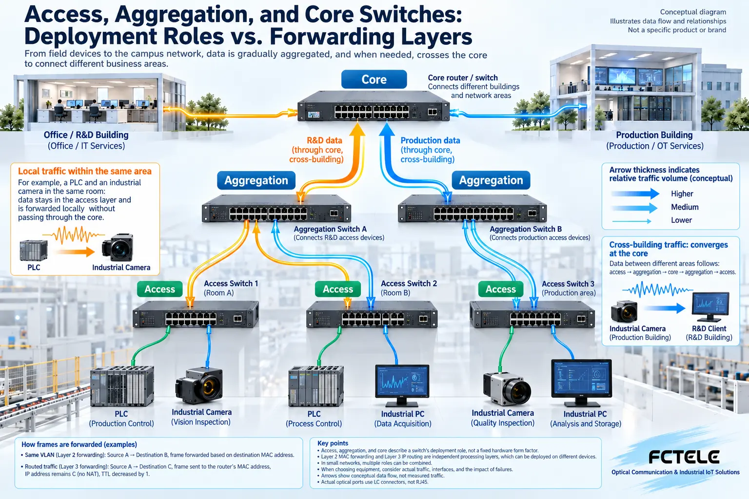
The core layer emphasizes the ability to connect important areas
The core usually carries backbone connections between multiple important areas. During design, the focus is on capacity, reliability, and maintenance impact. It does not automatically have some fixed performance just because it is called the core; the specific ports, switching capability, routing capability, and redundancy functions all depend on the product. An important position does not mean all traffic must detour to it and then return.
Large networks separate these roles to make responsibilities and failure scope clear; small sites can use a combined aggregation and core design. The number of layers needs to be judged together with scale, traffic, and maintainability. Adding devices also adds power supply, configuration, and failure points. You should not add unnecessary nodes just to make the naming complete.
Three deployment tiers are not the same as the three layers in protocols
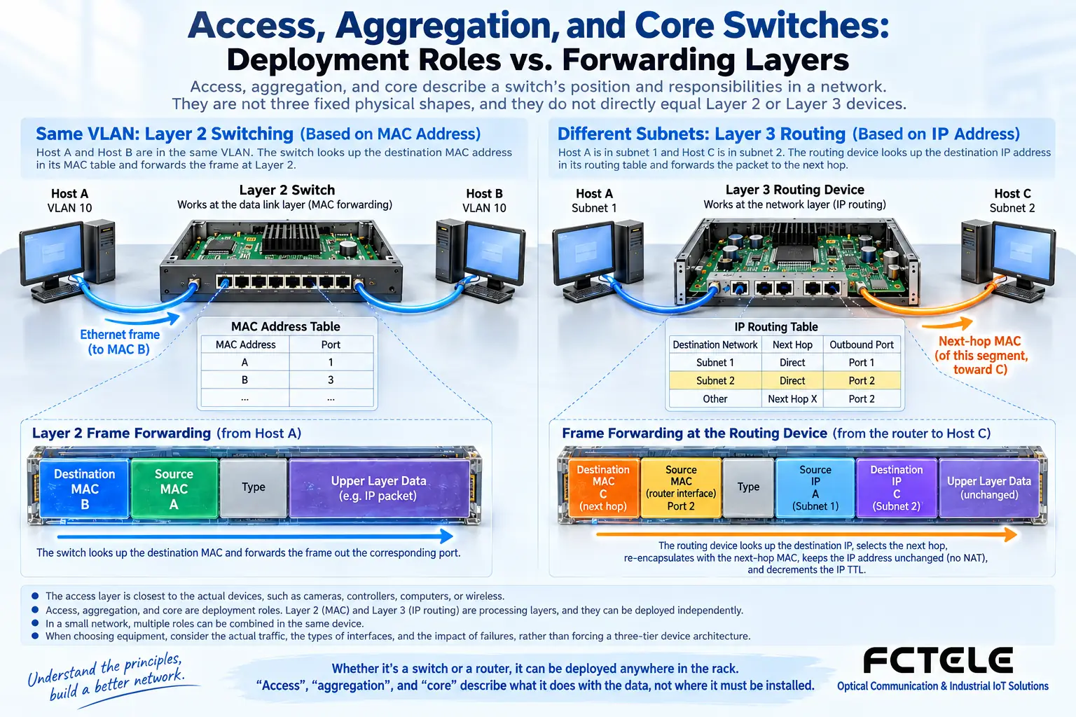
Layer 2 forwarding is mainly based on MAC addresses, which are the addresses used by Ethernet device interfaces, and it is constrained by the corresponding network scope. Layer 3 forwarding is mainly based on IP addresses and routing information, sending data to the corresponding network. The “layer” here discusses the protocol processing method, and it is not the same classification dimension as the three deployment roles of access, aggregation, and core.
An access device can have some Layer 3 capability, and a device located at the aggregation position may also mainly perform Layer 2 forwarding. Whether routing is needed depends on network segmentation and communication design, not on its upper or lower position in the rack. When selecting equipment, you should list deployment duties and protocol functions separately, and avoid treating a name as proof of capability.
Why MAC forwarding and IP routing should be understood separately
A Layer 2 device learns which port a source MAC address is located on, and then looks up where the destination MAC is located. When a Layer 3 device handles cross-network communication, it needs to choose the next hop based on the destination IP address, and use the address of the corresponding link for encapsulation to continue sending. The next hop can be understood as who this segment of the route is handed to first, but it does not mean the final destination IP address automatically changes because of this.
Ordinary routing forwarding and address translation are not the same function. You cannot draw all data passing through a Layer 3 device as having its source and destination IP addresses rewritten; address translation requires the corresponding function and design. For beginners, first grasp the basic difference that “MAC decides who this segment is handed to, and IP is used to judge where to go across networks,” then check the specific device’s supported capabilities. This will be clearer.
When calculating capacity, first find the exit that is truly shared
Suppose three access areas each have several video terminals, two of which send data to a central recorder, while the other mainly uses a local recorder. The shared exit toward the center mainly bears the traffic from the first two areas passing through it. You cannot unconditionally add all the local video from the third area as well. Conversely, when cross-area access or backup occurs, the path load may change again.
You should also consider burst traffic, bidirectional communication, and alternative paths during failures. Being sufficient under normal operation does not mean the remaining exit will also be sufficient after one link is interrupted. Capacity evaluation should include the main services and expected failure states, rather than using a fixed number of cameras as a universal threshold for whether core or Layer 3 equipment is needed.
Reliability should be designed around the scope of failure
An access switch failure may affect nearby terminals, an aggregation node failure may affect multiple areas, and a core node failure may affect a larger connection range. Whether backup equipment, independent power supply, and backup links are needed should be determined by these impacts. Two uplinks do not automatically form reliable redundancy. Without correct path control, they may instead cause looped forwarding.
Functions such as ring networking, spanning tree, or link aggregation supported by a device are not equivalent to one another and need to be checked according to the actual topology. During testing, you should also observe service recovery, not just whether the link lights up again. Recovery time and service loss should be based on the actual solution and testing. You cannot promise zero interruption just because the device is placed in the core position.
How Feichang Technology product details can be used for role selection
Feichang Technology 3325 and related industrial switch product details can serve as an entry point for checking port combinations, management functions, and installation conditions. The functions required on site should be matched item by item to a specific model, rather than inferring from “industrial switch” that it simultaneously supports all Layer 2, Layer 3, or backbone capabilities. If the page does not clearly state a certain function, continue to check the manual or confirm with the manufacturer.
On the access side, you can first check terminal interfaces, power supply, and on-site installation; on the aggregation and core side, combine the actual exit traffic, optical port configuration, and maintenance needs of important paths. Feichang Technology product features are meaningful only when they correspond to specific problems. For example, optical ports are used for uplink medium selection, and management capability is used for status observation. Do not write them as slogans that handle all network problems.
A communication table helps decide how many layers are needed
First list the terminals, servers, and areas, then record who communicates with whom, the main interfaces, traffic direction, and acceptable failure impact. When the network scale is small, one suitable device may take on multiple roles; after the scale expands, split responsibilities according to this table. Planning is not about first drawing three layers and then forcing all devices into them.
During acceptance, separately check terminal connections, intra-area communication, cross-area communication, and critical service paths. If backup paths are designed, you should also test failure states under authorized conditions. A handover document that clearly states the role and actual functions of each device is more helpful for later maintenance than simply attaching the labels “access,” “aggregation,” and “core.”
Verification materials:Feichang Technology industrial switches;Ethernet switching mechanisms. The diagram explains general mechanisms and is not a wiring diagram for a specific model.
Translated from the Chinese technical article. Source first published: 2020-09-28. Source last revised: 2026-10-13T20:43:40+08:00. Read the Chinese source
