


The abbreviation “analog fiber optic transceiver” easily mixes up analog video and current or voltage analog signals. The former may serve camera video, while the latter serves measurement interfaces for temperature, pressure, and so on; both contain continuously changing signals, yet they have different electrical ranges, processing methods, and business meanings. When choosing a product, you should write the complete object, and you cannot assume they are interchangeable just because the names are similar.
Analog first describes how a signal is expressed
A continuously changing voltage or current can represent brightness, sound, or a measurement value, and the specific meaning is defined by the interface system. CVBS video waveforms and four-to-twenty milliampere measurement loops can both be called analog, but they are not the same signal. After an analog input enters a device, it may also go through digital sampling and encoding before going onto the fiber. Therefore, being called analog video on the outside does not mean traditional analog modulation is necessarily used inside; and a device described as digital transmission does not mean the external interface must be a digital network. First distinguish the input object from the internal processing, and then discuss the principle accurately.
How traditional analog video optical transmission is modulated
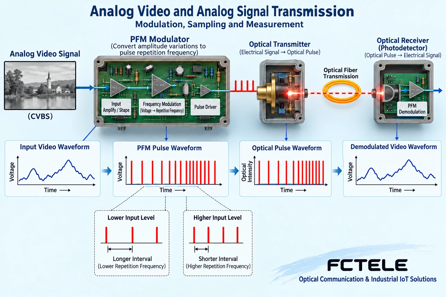
Some historical analog schemes use corresponding modulation to let the input amplitude affect carrier or pulse characteristics, then transmit over fiber and demodulate at the far end. In the teaching example of PFM pulse frequency modulation, what changes is the pulse occurrence frequency, not simply calling the pulse width frequency. The receiving side must have the corresponding demodulation capability. The figure in this article is used to explain this mechanism, and does not claim that all modern video fiber optic transceivers use PFM, nor does it invent internal circuits for an unverified model. The implementation of a specific product should be based on its documentation.
Digital video fiber optic transceivers add a sampling process
Applicable digital transmission schemes first convert the analog input into a digital representation, then transmit and recover it according to the device design. Sampling and processing must meet the input conditions, and overload or existing noise may enter the digital sequence as well. Digital transmission does not automatically make the source image clearer, nor does it guarantee compatibility with any video format. Input and output need to be checked against CVBS, SDI, or other specific objects, and a BNC connector cannot be treated as a guarantee of format. Modern selection should be based on the required interfaces and evidence, rather than broadly claiming that analog devices are necessarily bad or digital devices are necessarily lossless.
Four-to-twenty milliamperes represents measurement, not video
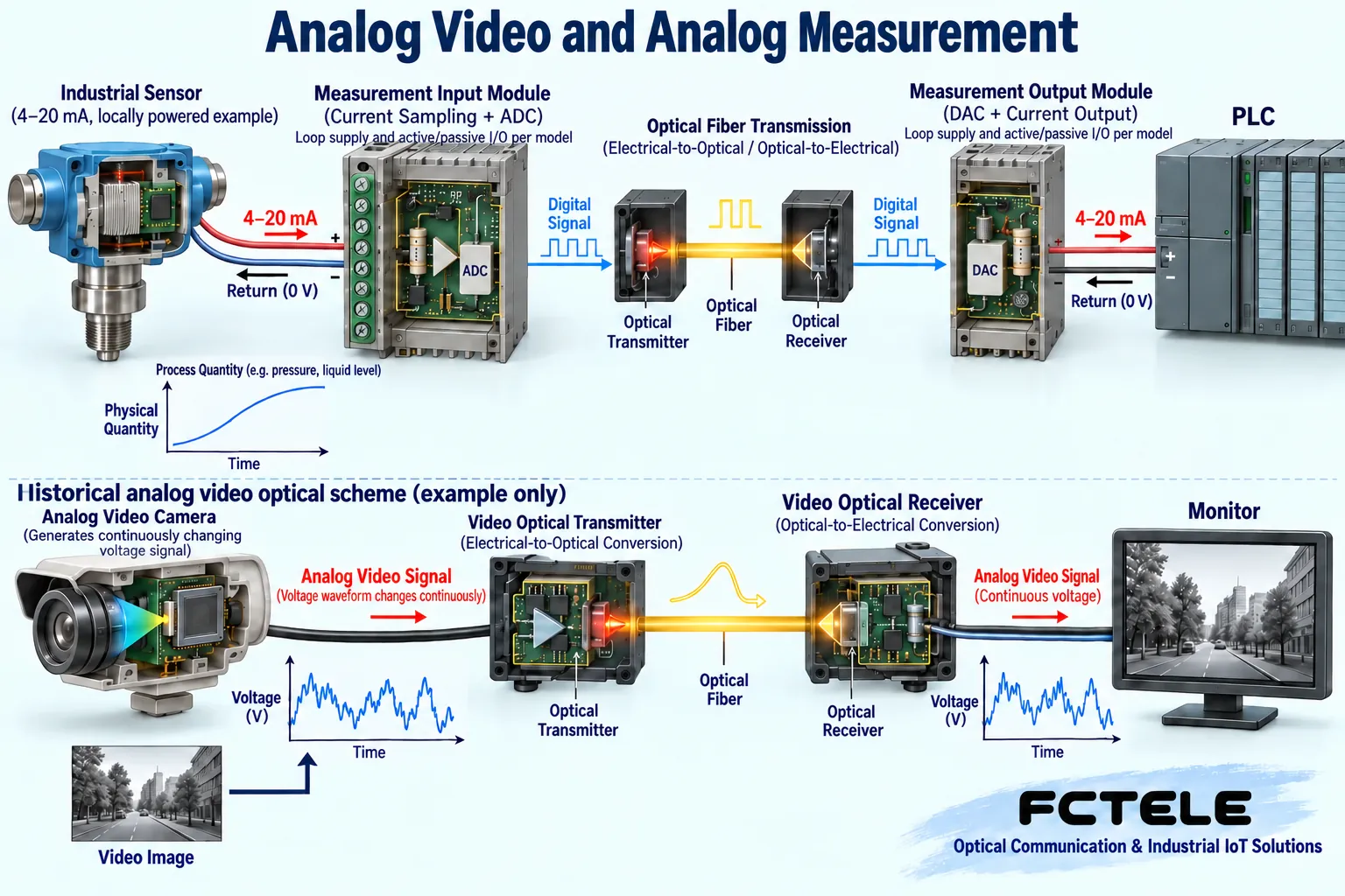
In industrial analog loops, a specified range of current can correspond to pressure, liquid level, or another quantity; how to convert it is defined by the sensor and system. Optical transmission equipment needs to receive the applicable analog quantity, then restore the specified output or data at the far end. Input and output types, ranges, loads, and power supply all need to match, and a video fiber optic transceiver cannot be directly connected to a measurement loop. Even if two devices are both marked four-to-twenty milliamperes, you must confirm who provides the loop power and the permitted conditions. Do not try to identify unknown ports by casually applying power.
Why does sampled digital data still need conversion?
After a sensor signal is sampled, it forms a digital code, and the engineering quantity must be obtained according to rules such as range, scale, and offset. Resolution, error, drift, and update speed are different indicators, and a larger number of bits cannot prove that the measurement is absolutely accurate. Restoring the output also involves the corresponding circuits and load conditions. For beginners, sampling is like writing a continuous reading as a numerical value, but the numerical value does not carry a natural unit. The list should note the range, permissible error, and response requirements, so that the device capability and the control system interpretation remain consistent.
Optical isolation does not remove local safety requirements
The middle section of the fiber does not form an ordinary electrical conductor connection, which helps with the corresponding span signal arrangement, but the measurement loops at both ends still have local power, grounding, and protection. You cannot claim that the entire system is absolutely lightning-proof or requires no safety grounding just because fiber is used. If a device has electrical isolation, it must also be understood according to the actual rating, ports, and conditions. For high potential, near strong electricity, or safety-related measurements, it should be implemented according to professional design and standards. The current loop and chip diagrams in the article are functional illustrations and do not replace specific terminal wiring and construction drawings.
How should Feichang analog signal products be cited?
The official website of Feichang FCP-A4 describes the optical transmission direction for one to four channels of analog current or voltage. This is a verifiable example of an industrial measurement product, not a CVBS analog video fiber optic transceiver. When ordering, you need to confirm the actual input and output ranges, channels, and corresponding configuration, and you cannot assume from the name that every unit simultaneously supports any current or voltage signal. For camera solutions, you should check the video fiber optic transceiver details. Putting specific Feichang products under the correct object is a useful feature description; mixing the two categories only makes selection and maintenance more difficult.
How to verify that the measurement link has not changed the meaning
Suppose you want to send a liquid level sensor signal to a remote PLC. First check the sensor output and the PLC input, then confirm the range and loop arrangement at both ends of the optical transmission device. Under safe conditions, use a suitable test source to provide multiple known points, and compare the original signal, the restored output, and the PLC engineering value. You cannot judge full-range accuracy by measuring only one intermediate point, nor by merely observing whether there is a number. This is a hypothetical verification method, not a customer site record. Formal accuracy and calibration requirements should be determined by the actual system and metrological conditions.
Video links should use a different acceptance method
If the task is analog camera transmission, you should check the video format, image, synchronization, continuous operation, and applicable control channels, rather than using the calibration method for a measurement loop. Image abnormalities can be checked segment by segment from the source input, coaxial cable, optical link, and recording end; measurement abnormalities require looking at range, loop, current, and conversion. Both systems have fiber, but that does not make fault diagnosis the same. Define the business object first and then choose the test, which preserves valid evidence and avoids uniformly replacing optical modules or increasing power whenever a fault occurs.
Do not write only “analog fiber optic transceiver” in the product list
The list should use complete names, for example a video fiber optic transceiver for the corresponding format, or a current and voltage analog signal fiber optic transceiver with a specified range. Attach the source-end and receiving-end models, channels, directions, input and output conditions, power supply, and acceptance results. Internal modulation or sampling mechanisms should be described for a model only after clear information is obtained. The key to understanding analog is to ask what it represents, how it is processed, and how it is restored. In this way, you can understand the principle diagram and also place Feichang products in the correct position, rather than making a wrong connection based on a vague abbreviation.
How are analog values and video images accepted separately?
Industrial analog quantities care about the actual value and error corresponding to a certain input after restoration at the far end; video services care about image format, timing, clarity, and continuity. Even if both go through sampling, the test methods are different. Measurement channels need a suitable calibration source and instruments, and you cannot conclude that accuracy is acceptable just because you see a waveform. Video links need real images and motion scenes, and you cannot use a current reading to replace acceptance. Clarify the business object first, then choose the inspection tool, so you can avoid being confused by the same word “analog.”
PFM only explains the corresponding historical video scheme
Pulse frequency modulation can use the frequency at which pulses appear to express input changes. It is one mechanism of a corresponding analog transmission scheme, not a common internal implementation of all fiber optic transceivers. Modern products may use sampled encoding and digital multiplexing, and may also face completely different interfaces. Therefore, when you see a PFM illustration, you can only understand that limited scenario. You cannot infer from it the entire principles of E1, RS485, Ethernet, or industrial current fiber optic transceivers. What method a product actually uses must be based on specific documentation, and a technical introduction from an old article should not be generalized to the entire company product line.
Feichang measurement products require checking the input range first
Official website FCP-A4-type analog signal transmission products are aimed at corresponding current or voltage channels, and when using them you must confirm the input and output form, range, number of channels, and power supply. It is not an analog video device, and connecting a camera BNC will not automatically transmit images. Suppose the sensor outputs a certain current; you also need to confirm the form expected by the remote instrument and the load conditions. The example only explains the checking method and does not provide terminal wiring that can be directly used in all sites. When industrial control loops are involved, arrange shutdown and safety verification to avoid test operations causing actual actuator misoperation.
Product and principle verification materials: Feichang product details 787. The general mechanisms and hypothetical examples in the main text do not replace the corresponding model manual.
Translated from the Chinese technical article. Source first published: 2020-01-08. Source last revised: 2026-10-13T13:28:52+08:00. Read the Chinese source
