


An audio optical transceiver mainly sends sound signals from a compatible audio interface to the far end; a telephone optical transceiver, besides transmitting voice, also needs to handle telephone-interface-related power supply, ringing, and on-hook/off-hook status. Both may use optical fiber, and both may digitize sound, but they cannot replace each other just because both can carry sound. When selecting a model, first look at the devices and interfaces being connected, not just count how many channels of sound there are.
First determine whether you are connecting audio equipment or an ordinary telephone
Devices such as mixing consoles, players, and power amplifiers usually exchange sound signals through the corresponding audio interfaces. An ordinary analog telephone, however, needs the telephone line to provide the corresponding working conditions: when someone calls, the telephone must ring; after the handset is picked up, the line must recognize the off-hook state; during a call, both parties need to hear each other. Sound is only one part of it; the call status must also be transmitted correctly.
Therefore, using the same two wires or similar plugs does not mean the electrical meaning is the same. A telephone interface may have power supply and ringing voltage, and it cannot be casually connected as an ordinary line audio port. Before the project starts, each endpoint should be written down clearly: is it a mixing console output, a power amplifier input, a telephone exchange line, or an ordinary telephone set. This endpoint list is more useful than vaguely writing “transmit audio.”
How audio changes from an electrical signal into an optical signal and back again
Taking a digital audio optical transceiver as an example, the sending end first samples the analog sound signal, recording the waveform’s amplitude at different points in time, and then converts the amplitude into digital values. Sampling is like continuously taking snapshots of the waveform, but it cannot be understood as meaning that taking a few photos can unconditionally restore all sound; the sampling rate, filtering, and allowed frequency range all have limits.
The digital sequence enters the optical transmitter through the device’s transmission circuit and reaches the other end through the optical fiber. The receiver restores the data, and then the digital-to-analog conversion circuit forms an analog sound signal. What is transmitted in the optical fiber is not a floating sound wave picture, but optical changes corresponding to digital data. The transmission format, optical interface, and channel organization at both ends must be compatible; you cannot just check whether the connector can be plugged in.
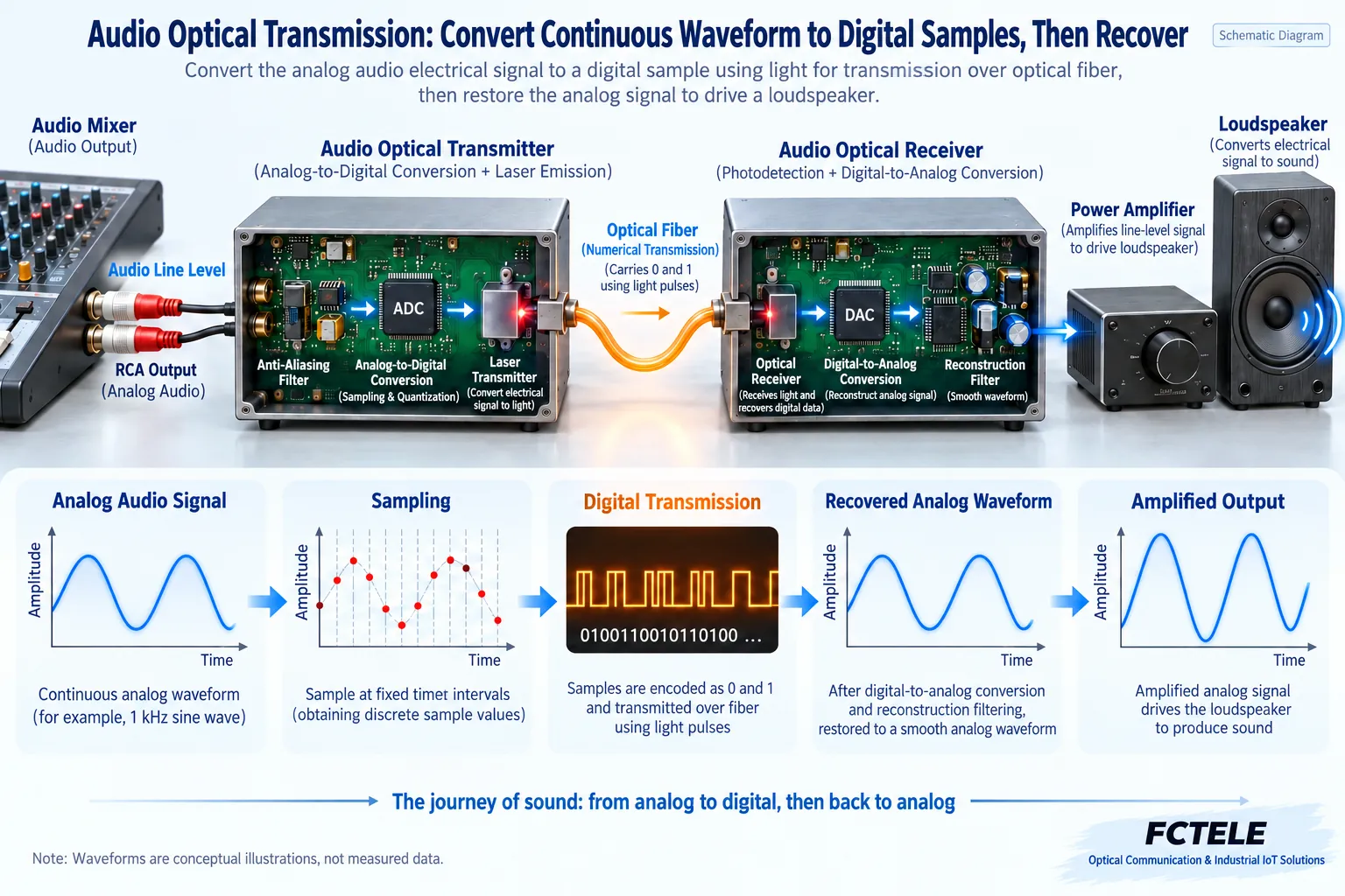
Sampling rate and bit depth are not the same specification
The sampling rate indicates how many time points are recorded per second, and the bit depth indicates how many bits are used to represent each sample. The former affects the range of signal frequencies that can be represented, and the latter affects how finely the amplitude is quantized. Neither is a guarantee that “all sound will definitely sound better”; the input circuit, noise, distortion, signal level, and actual usage conditions also affect the result.
If the input is already overloaded and clipped, the optical fiber behind it will not recreate the lost waveform details. No matter how high the sampling parameters are, they cannot repair incorrect wiring or an excessively large input signal. You should first check the allowed level of the audio interface and the device connection method, and then discuss digitization parameters; the parameters in product details should also be understood with the correct units, and bit count, number of samples, and transmission bit rate should not be confused with one another.
Why line audio output usually still needs a power amplifier
A line-level audio port is mainly used to pass the signal to the next audio device, not to directly provide enough power to a passive speaker. If an ordinary passive speaker is used at the far end, a matching power amplifier is usually still needed; if a powered speaker is connected, its input interface and level requirements must be checked. “The optical transceiver has restored the sound signal” and “it drives the speaker to make sound” are different stages.
For example, a background music project can have a player output to an audio optical transceiver, and after the far end restores the line audio, it goes into a power amplifier and then connects to speakers. When troubleshooting, observe section by section along the player, sending end, optical fiber, receiving end, power amplifier, and speakers. You cannot immediately conclude that the optical fiber is broken just because there is no sound at the far end; power amplifier mute, wrong input selection, or volume settings may also be the cause.
Telephone interfaces also require a correct understanding of FXS and FXO
FXS can be understood as the side that provides analog telephone line service, and an ordinary telephone usually uses these services through an FXO interface. The subscriber line of a telephone exchange generally belongs to the FXS side that provides service. Therefore, in a telephone line extension scenario, the optical transceiver near the exchange line usually needs a matching FXO interface, and the side at the far end connecting to the telephone usually needs a matching FXS interface.
This shows that the role is determined by the connected object, not fixed by the names “sending end” and “receiving end.” A telephone call itself is a bidirectional service, and it cannot be drawn as if sound always travels in only one direction. Statuses such as ringing and on-hook/off-hook must also be handled according to the device’s supported method, and the actual interfaces at both ends should be based on the model’s manual.
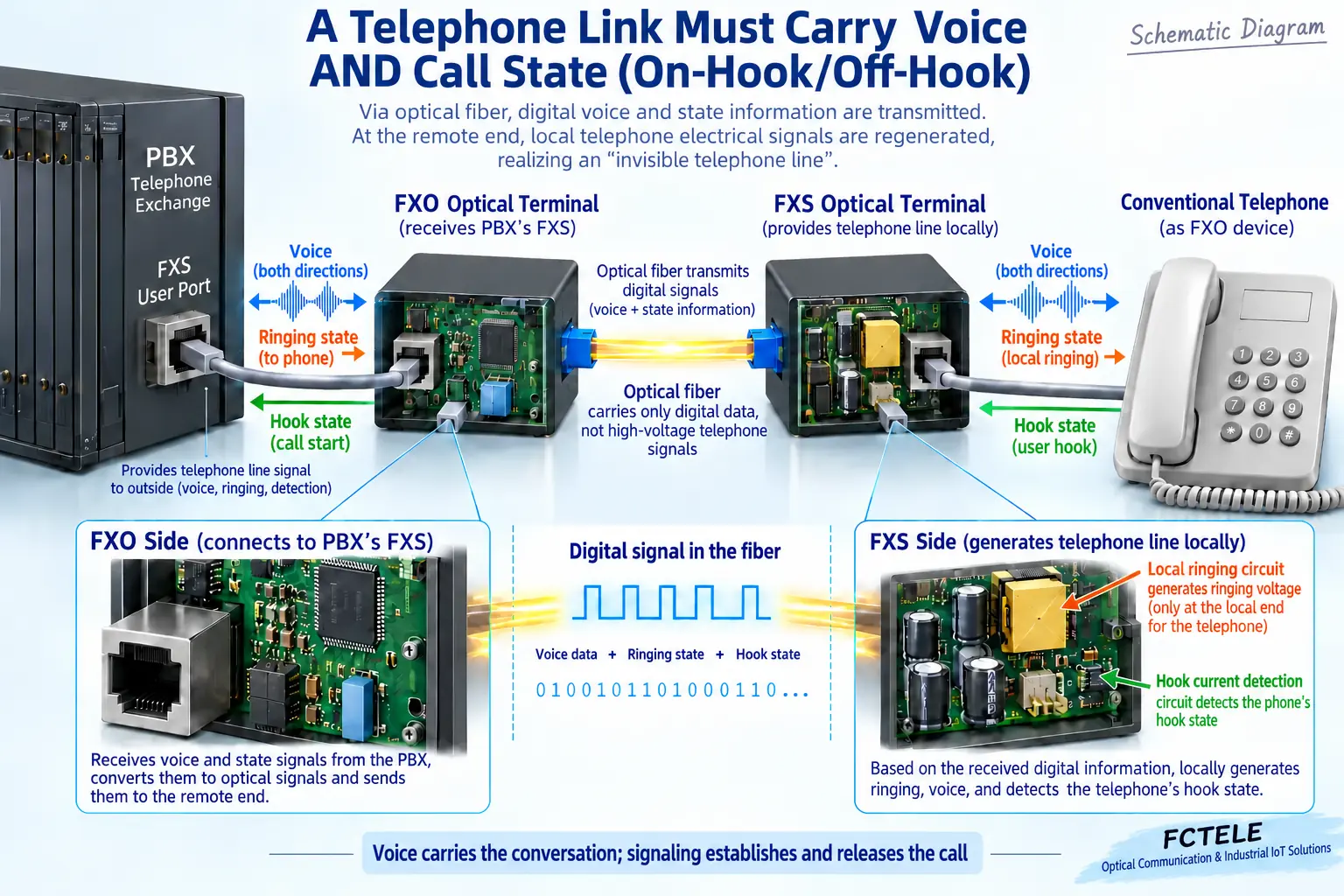
Ringing and line power supply do not flow directly through the optical fiber
What the optical fiber transmits is information encoded by the device; it does not conduct the electrical energy of the telephone line from one end to the other. The far-end device uses its own power supply and, according to the received call status, forms the required interface behavior. The ringing signal comes from the service side, while the on-hook/off-hook status needs to be returned from the user side; these information directions are clearly different from one-way background music.
Functions such as caller ID, fax, or polarity reversal may also have separate compatibility conditions. The fact that a device can transmit voice does not mean all these functions are supported. Nor can “bidirectional audio” be treated as meaning that the complete telephone service has passed acceptance; actual incoming calls, outgoing calls, hanging up, and any additional services required by the project should all be tested separately.
PCM is a processing method, not a product name with a fixed capacity
PCM stands for pulse code modulation and is often used to convert analog sound into a digital sequence. Telephone voice and audio equipment may both use this type of method, so seeing the letters PCM does not determine whether it is a telephone optical transceiver or an audio optical transceiver. Exactly how many interface channels the system provides also depends on the transmission structure, bandwidth, and specific configuration.
You cannot say that all telephone optical transceivers have a fixed 30 channels, nor can you directly extend the channel count of one multiplexing system to all devices. Mono, stereo, and the number of telephone lines are also not the same counting basis: stereo usually includes two audio channels, left and right, while one telephone line also involves call status. The selection checklist should clarify how the manufacturer defines “one channel.”
Which specific features can be checked in Feichang Technology products
The Feichang Technology FCA-A4-L product details list RCA audio interfaces and parameters related to digital audio sampling and conversion, which are suitable for checking line audio transmission requirements accordingly. Its audio port cannot be assumed to connect to an ordinary telephone just because the transmitted content includes human voice. Sampling parameters should also be confirmed together with the on-site interface level, direction, and channel configuration.
The Feichang Technology FCP-O16 and FCP-S16 telephone optical transceiver details list telephone interface configurations related to 1 to 16 channels and introduce features such as caller ID and fax. Actual purchasing should confirm the FXO and FXS combination and the required additional functions; the options in a product series cannot be understood as meaning that all configurations have them. The features of the two types of products should be explained around their respective interfaces, and they should not be written as one universal sound transmission device.
Use two scenarios to verify whether the right device was selected
In a background music scenario, check the input audio level, mono or stereo, transmission direction, and the far-end power amplifier; in a telephone extension scenario, check the exchange subscriber line, the far-end telephone, the interface roles, and the call functions. Even if the installation distance is the same, the two projects may require completely different devices. Optical fiber is only the common transmission medium; it does not unify their service meanings.
When accepting an audio link, first use known-good input and output devices to observe the sound, then check noise, distortion, and left-right channel correspondence. When accepting a telephone link, separately test incoming calls, outgoing calls, ringing, on-hook/off-hook, and any additional services required by the project. When testing telephone interfaces, follow the device instructions, and do not use ordinary audio test lines or hand contact to judge live lines; when checking optical ports, appropriate instruments should also be used, and you must not look directly at the optical fiber end face.
Reference materials:Feichang Technology digital audio optical transceiver;Feichang Technology FCP-O16/S16 telephone optical transceiver;ITU-T G.711. The diagram explains general mechanisms and is not a wiring diagram for a specific model.
Translated from the Chinese technical article. Source first published: 2019-08-13. Source last revised: 2026-10-13T14:07:46+08:00. Read the Chinese source
