


Telephone optical transceivers should be classified by telephone access method, transmission interface, and service combination, not by which industry they appear in. The same device can belong to multiple categories such as multi-channel, rack-mounted, and network-managed at the same time; these terms are not mutually exclusive. Video optical transceivers and cable television optical transmission cannot become subcategories of telephone optical transceivers just because they all use optical fiber.
First identify the device by the service goal
When a customer wants to extend an ordinary telephone extension to a remote location, what is needed is not only a voice channel but also line behaviors such as calling, ringing, and on-hook/off-hook detection. Telephone optical transceivers handle access, information organization, optical transmission, and remote restoration around this type of service. Camera video, television radio frequency, and ordinary telephone have different interfaces and control methods, and they cannot be interchanged just because they are all called optical transceivers.
When determining the category, first write down what devices are at both ends, then write down the service to be completed. For example, one end is a PBX analog extension port and the other end is an ordinary telephone, versus one end delivering an E1 digital trunk and the other end connecting to telephone access equipment, are two different interface conditions. Industry names can only indicate the usage scenario and cannot replace wiring and compatibility judgments.
By telephone interface: ordinary analog and special interfaces
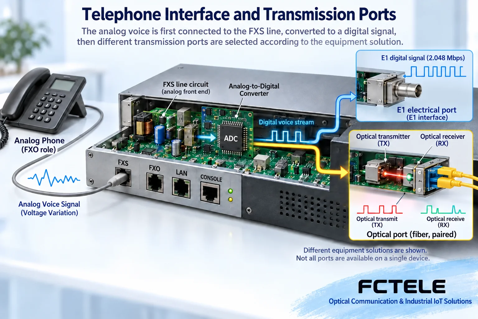
Analog telephone extension often uses FXO and FXS roles. FXO connects to an interface that already has subscriber line conditions, while FXS provides the corresponding feeding, ringing, and detection for an ordinary telephone. The device sends voice and status information over the optical path, and at the remote end uses local interface circuits to perform line behaviors. Optical fiber does not directly deliver telephone electrical power to the other end, so power supply at both ends is also part of the solution.
Two-wire or four-wire audio, E&M, magneto telephone, and other interfaces have different electrical and control conditions, and the specific product configuration should be checked. Dedicated digital extensions and IP telephones cannot be assumed to connect to ordinary analog telephone ports. Interface categories solve whether and how a connection can be made, not how many identical-looking sockets are on the housing.
By transmission side: paired optical line and digital tributary
Some devices have both ends directly connected by a matching optical line; some telephone access equipment first aggregates voice channels into digital tributaries such as E1, which are then carried by another transmission system. The former requires confirming the paired devices, fiber type, wavelength, and line format, while the latter also requires checking the E1 electrical interface, framing, clock, and signaling. Even if the interface names on both sides are the same, it does not mean all layers are compatible.
The E1 line rate is 2.048 Mbit/s, but it cannot be asserted from this that any device provides 30 telephone ports. In traditional E1 channel-associated signaling telephone configurations, some time slots are used for frame synchronization and signaling, and 30 are used for voice; multiple E1, different signaling, or paired dedicated optical lines must be confirmed according to the actual structure. Saying that G.703 is all the service protocols of a device is also inaccurate; it mainly specifies the physical and electrical characteristics of the relevant digital interface.
By service combination: pure telephone and integrated services
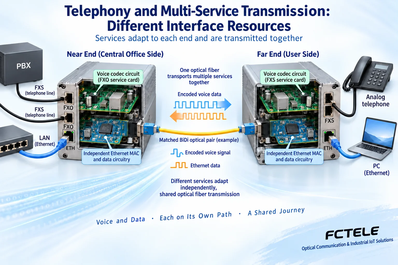
Pure telephone solutions focus on voice channel extension; integrated service devices may also be configured with Ethernet, serial ports, E1, or other services. Different interfaces first pass through their own adaptation circuits and are then transmitted together, rather than all signals being directly connected to one line. The number of services, direction, bandwidth allocation, and simultaneous operation capability must be stated in the model documentation.
Multi-service can reduce duplicate equipment, but it may also share the chassis, power supply, and optical path, so one common fault can affect multiple services. A working telephone does not prove that network data is already available, and a lit network light does not prove that telephone signaling is correct. When video, data, and audio are listed as optional services, one cannot arbitrarily describe a pure telephone device as having all of them.
Installation and management are two other dimensions
Desktop, wall-mounted, DIN-rail, and rack-mounted are installation forms; fixed ports and pluggable cards are expansion methods. They affect space, wiring, power supply, and spare parts, but they do not automatically change the service interfaces. Network management capability is used to view configurations and alarms, and it does not necessarily mean that telephone service runs over IP; two optical ports do not by themselves establish automatic protection.
Single-fiber bidirectional and dual-fiber bidirectional describe the optical path structure. Single-fiber requires matching transmit and receive wavelengths, while dual-fiber usually connects the local transmit to the remote receive. Both must check the optical power range and actual link loss, and one cannot infer longer distance, greater stability, or zero interruption from the words single-fiber or rack-mounted.
Turn the classification into a purchasable configuration
In the Feichang Technology pure telephone series, FCP-O16/FCP-S16 give the corresponding voice channels and FXO/FXS relationships, which can be used for configuration verification of small-scale analog extension. For integrated service categories, specific models should be checked separately; a category page can only help find products and does not mean that all members have the same number of services and management functions.
The requirement can be written as: a certain number of analog extensions, the interface roles at both ends, the required concurrency, existing optical cores, and installation power supply, then list whether E1 or data services are needed. The supplier confirms the model and both-end configuration according to this list, tests call and release channel by channel on site, and then tests all required services running simultaneously. This makes it easier to obtain a verifiable solution than asking generally which type of optical transceiver is more advanced.
A procurement example: same requirement, category may still differ
Assume a project needs twelve ordinary analog extensions, has dedicated optical fiber, but no ready-made E1 delivery. Priority should be given to explaining the telephone interfaces at both ends and the paired optical line conditions to the supplier; one should not skip the condition of how the digital tributary is obtained just because a certain E1 device also happens to be marked with twelve channels. If there is already usable E1 transmission resource on site, then telephone PCM access can be evaluated separately, checking signaling, clock, and channels. The two routes solve similar services, but the procurement composition and acceptance responsibilities are different.
If the project later adds an instrument serial port, first determine whether the original pure telephone device explicitly supports expansion, then compare the cost and impact of adding independent transmission versus changing to integrated services. New capabilities are not obtained by simply relabeling old equipment as multi-service. During maintenance, also check whether power, chassis, and optical path are shared, and confirm how many services one fault will affect. The meaning of classification is to help customers ask the right questions about interfaces and resource conditions, not to put all seemingly related articles or devices into one big category.
References:Feichang Technology product document 1;Feichang Technology product document 2;Feichang Technology product document 3;Principle and standard document 4;Principle and standard document 5. The schematic diagrams are general principle illustrations, not actual products, customer cases, or measurements. Interfaces and specifications are subject to the ordered configuration and on-site acceptance.
Translated from the Chinese technical article. Source first published: 2019-08-13. Source last revised: 2026-10-13T14:07:46+08:00. Read the Chinese source
