


“Beyond-100G fiber transceivers” easily make people think of simply increasing the speed of a small 100M box. In reality, when entering high-speed interconnects such as 200G and 400G, what customers face is often a high-speed pluggable optical module on a switch, together with its host port, cabling, heat dissipation, and error-correction mechanisms. Different selection targets require different verification methods. This article explains why high-speed optical transceivers are difficult, and which conditions cannot be omitted in procurement and acceptance.
Higher speed is not simply making the laser brighter
The module first receives the high-speed electrical signal sent by the host, then through processing and driving, loads the information onto an optical signal. The far-end detector converts the received light into an electrical signal, and the receive circuit then recovers the data. Increasing speed means distinguishing more information in a shorter time, and the tolerance for noise, waveform distortion, clock error, and thermal design shrinks. Simply increasing transmit power cannot solve these problems, and may even overload the far-end receiver.
The total rate can be achieved jointly by multiple channels. For example, a certain 400G solution uses four line channels of nominally 100G each, but this does not mean that all 400G modules internally have only four lanes, nor does it mean that these channels necessarily correspond to four external fibers. The host-side electrical channels and the line-side optical channels may be organized differently, and the complete module standard must be checked; one cannot judge by the enclosure name.
Why PAM4 improves efficiency but is also more afraid of noise
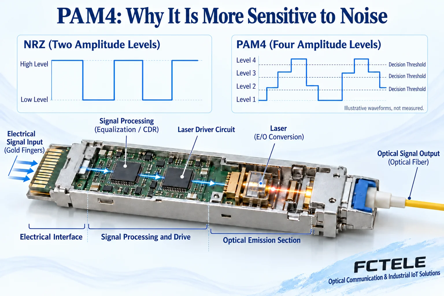
Traditional NRZ signals use two levels, high and low, to express information, with each symbol representing one bit. PAM4 uses four amplitude levels, and one symbol can express two bits of information; at the same symbol rate, this increases the amount of information carried per symbol. But the spacing between the four levels is smaller, and the receive circuit must distinguish more boundaries, so the same amount of noise or distortion is more likely to cause misjudgment.
This does not mean PAM4 is necessarily “unreliable,” but reliable operation depends on complete link design. Driver linearity, detector and amplifier circuits, equalization processing, clock recovery, and error-correction configuration can all affect the result. The levels and light beams in the figure are simplified illustrations for easier understanding; they do not show a real eye diagram or measured values, and one cannot claim a certain model’s bit error rate based on the graphic.
What equalization, clock recovery, and FEC each handle
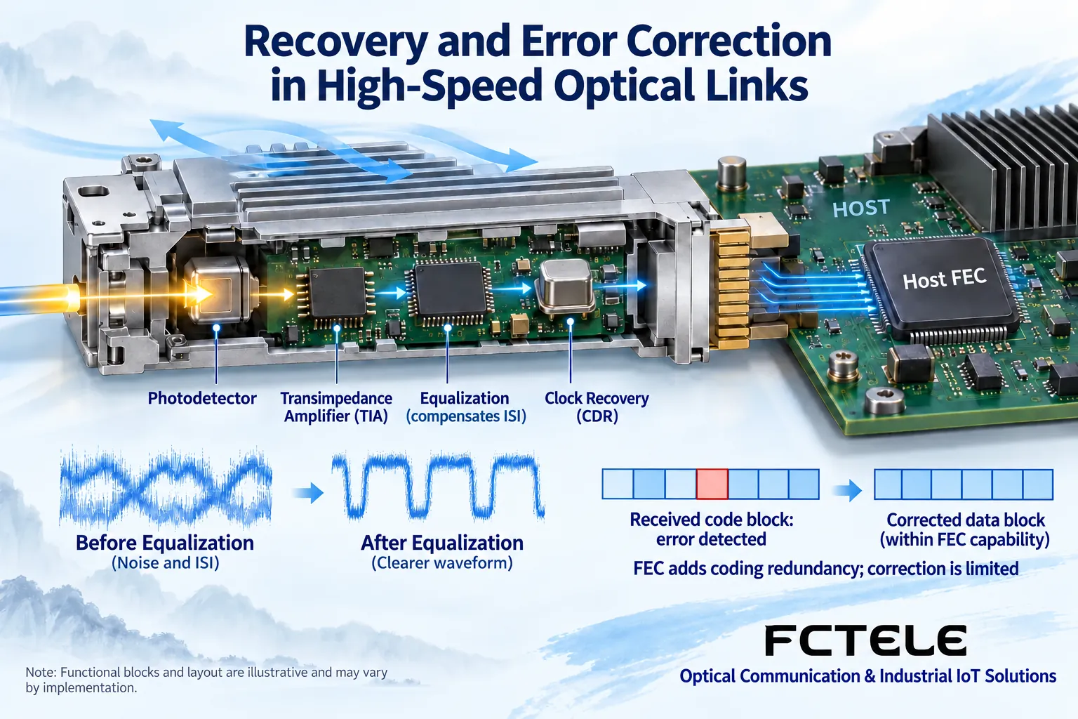
Equalization can be understood as compensating for waveform distortion caused by the channel, rather than “wiping away” all noise. Clock and data recovery, often written as CDR, helps the receiver determine the appropriate sampling instant; if the instant deviates, data that could originally be identified may also be misread. The specific location and combination of these functions vary by host and module architecture, and the schematic cannot be treated as the circuit diagram of all products.
Forward error correction, abbreviated FEC, is a mechanism in which the transmit side adds specified redundant information, and the receive side detects and corrects errors within a certain range according to corresponding rules. It is not insurance that communication can still be maintained when errors increase without limit. Some high-speed module solutions require the host to enable the corresponding FEC, and the modes at both ends and the device support range must match; one cannot simply see that a module says 400G and then disable error correction in pursuit of so-called low latency. After the error-correction capability is exhausted, uncorrectable errors will still occur.
Parallel optics, WDM, and breakout connections cannot be chosen interchangeably
Some parallel optical solutions place each channel on a different fiber core, requiring the corresponding multi-fiber connector and correct polarity; WDM solutions combine different wavelengths into the fiber core in the same transmission direction, and the common external connection form is different again. Taking 400G as an example, names such as DR4 and FR4 express different line conditions, and one cannot directly interconnect just because the total rate is the same. Transmission distance, fiber type, wavelength organization, and connectors must all be consistent or confirmed according to a clear interoperability plan.
A breakout connection splits one high-speed host port into multiple lower-speed ports for use, and it does not mean that an ordinary optical module can naturally support one-to-many. Whether the host supports breakout, which mode it supports, and whether the module and cable cooperate must all hold true together. If the customer wants point-to-point interconnection, the complete mode at both ends should first be ensured consistent; if breakout is wanted, the target port count and rate should be written into the requirements, rather than only buying a part “compatible with 400G.”
Temperature and power supply are link conditions, not decorative extras
The processing circuits and optical components of high-speed modules consume power and generate heat. The module power allowed by the switch port, heat sinks and airflow direction, density of adjacent ports, and ambient temperature jointly affect continuous operating capability. The rated temperature of the equipment room is not equal to the internal temperature of the module; when temperature reading is supported, it should be judged together with the manual thresholds. One cannot assume suitability for high-temperature industrial sites just because of a metal enclosure or the presence of a heat sink.
The ordinary Ethernet optical transceiver models on Feichang Technology’s official website cannot be directly used as proof of 200G or 400G capability. This material has not verified corresponding beyond-100G Feichang Technology models, so this article does not promise that Feichang Technology has a certain high-speed module, specific certification, or cross-brand compatibility. If a project needs this rate class, the host model, port standard, and line conditions should be provided, and then the supply plan should be confirmed according to verifiable product information.
Acceptance should not leave only “the light is on and it can ping”
Acceptance records should include the complete part numbers of the host and module, software version, port rate, breakout mode, FEC configuration, cable type, and polarity. After power-on, confirm that the link is established, then check diagnostic temperature and optical power, port errors, and available error-correction statistics. No packet loss after error correction does not mean that errors continuously rising before correction can be ignored; nor can the counting conventions of different devices be directly compared as a horizontal ranking of advantages and disadvantages.
Carry out continuous bidirectional service testing under the specified load, recording repeated link establishment, temperature rise, and error changes. When swapping parts for troubleshooting, change only one condition at a time; first check the matching relationship, end faces, and fiber cores, then check device support and thermal conditions. Only conclusions obtained this way can be used for delivery and maintenance, rather than relying on one occasional successful communication.
Material note: The illustrations are general mechanism diagrams, not actual photos, teardowns, or test reports of specific modules. Reference Cisco 400G module data sheet for line types and host conditions; specific projects are subject to actual model information and support lists.
Translated from the Chinese technical article. Source first published: 2025-02-12. Source last revised: 2026-10-13T14:18:10+08:00. Read the Chinese source
