


Keep the E1 terminal and replace the transport network with IP
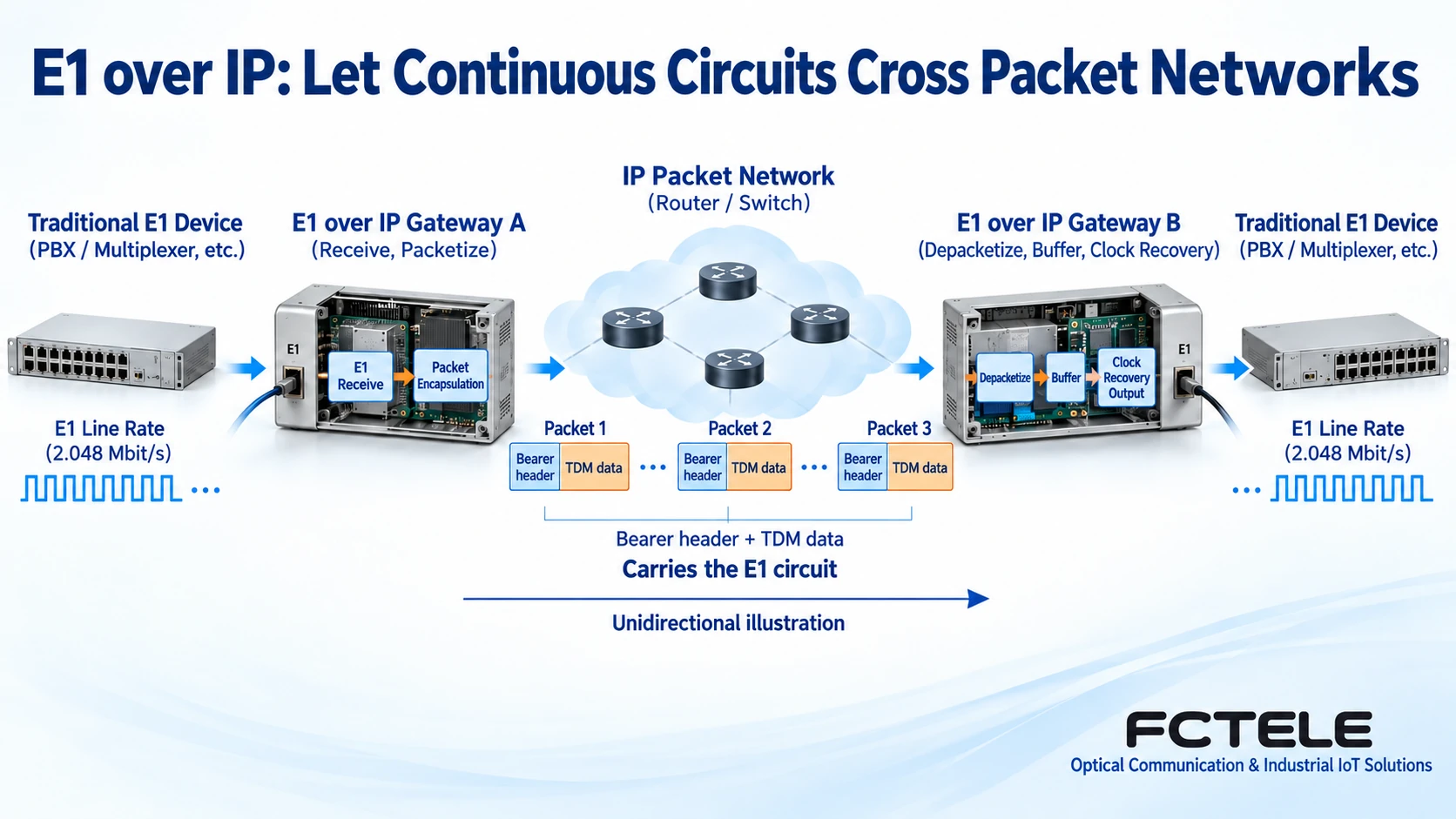
When old equipment at one end still outputs E1 and the other end must also receive E1, but only an available Ethernet or IP network exists in between, E1 over IP circuit emulation can be considered. Gateways at both ends segment the continuous E1 data into network packets, and after delivery they output an E1 signal that conforms to the selected service mode. What is continued is the circuit interface, not a transformation of the old equipment itself into Ethernet equipment.
To understand the convergence of traditional circuits and IP networks, you first need to distinguish service frames, bearer packets, and line timing. G.704 defines related frame structures, not an IP encapsulation protocol; the management system uses NTP to calibrate date and time, and this cannot be used to conclude that the E1 line clock already meets service requirements.
What is the difference between a continuous beat and packet-by-packet forwarding?
E1 continuously sends bits at a fixed line beat, and the receiving device relies on this beat to read the data. An IP network forwards packets one by one, and packets go through switching, queuing, and possibly changing paths. Even if the average bandwidth is sufficient, several packets may arrive crowded together, followed by a temporary absence of packets. This variation in arrival spacing is called packet delay variation.
On the sending side, the gateway first receives E1 data, cuts it into segments according to the configured payload length, and then adds the required bearer header and channel identifier. The receiving side identifies the corresponding service, checks packet order, extracts the TDM data, and restores the output. TDM means transmission arranged by time; a pseudowire is a bearer mechanism that emulates a connection over a packet network, and does not mean that a dedicated physical line has been laid.
SAToP and CESoPSN: the choice is how the circuit is handled
RFC 4553 describes SAToP, which carries a TDM bitstream without parsing the service frame structure, and is suitable for corresponding scenarios that need to transport an entire circuit. RFC 5086 describes CESoPSN, which involves structured sixty-four kilobit service channels. The two handle services differently, and you should not assume that configurations are interchangeable just because both are labeled E1 over IP.
When selecting a model, check the bearer methods, encapsulation, payload length, frame and signaling settings, channel mapping, and firmware versions supported at both ends. Standard names can only help you understand the mechanism; they cannot replace product interoperability confirmation. This article uses a generic slicing process as an illustration and does not claim on that basis that a particular Feichang Technology model already supports all RFC modes.
The jitter buffer lets data be output at the required beat, but it also introduces waiting
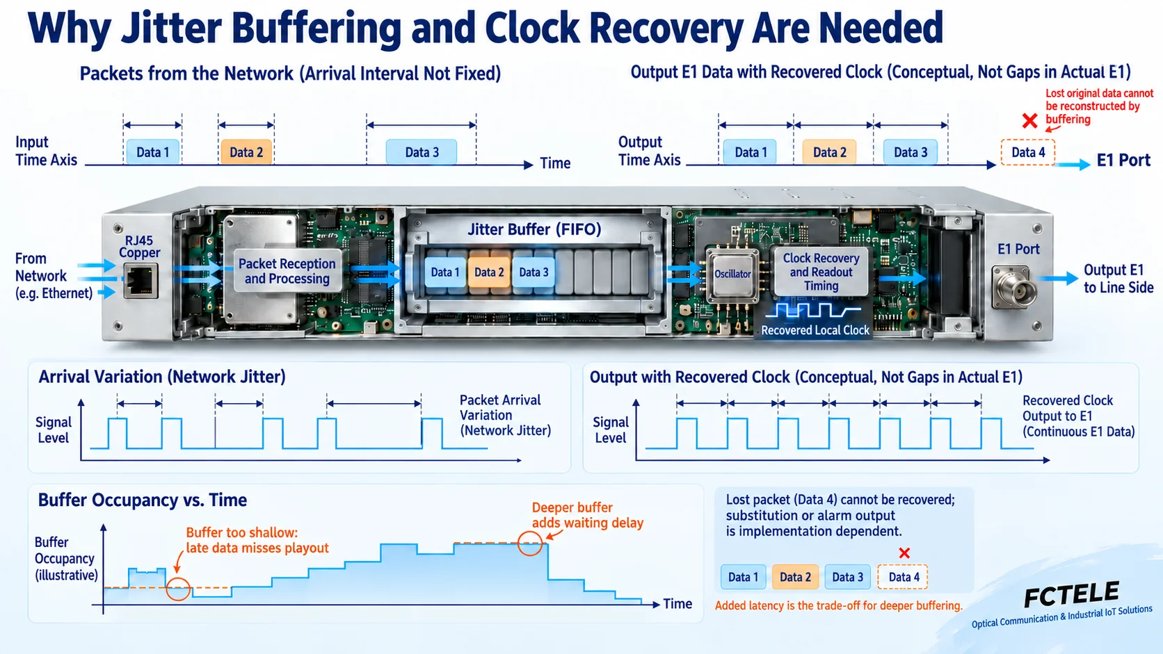
The receiving gateway temporarily stores data that arrives early and then reads it out at the required beat; this is the jitter buffer. It leaves some margin for packets that arrive later. If the buffer is set too shallow, late data may miss the output timing; if set too deep, end-to-end waiting time also increases. The basis for selection should be actual network fluctuation and the latency allowed by the service, not simply setting the value to the maximum.
Buffering cannot recreate data that has already been lost. Network congestion, packet loss, or a long outage may cause corresponding service impairment, substitute output, and alarms, and the specific behavior depends on the device implementation. Out-of-order packets can also cause problems if they exceed the device’s handling capability. Therefore, “can pass through an IP network” and “maintains the original quality in any network” are not the same conclusion.
The recovered clock determines how the remote end continues to read out
In addition to reconstructing data, the receiving side also needs to establish a suitable output clock. The system may use a common reference clock, or it may perform adaptive recovery based on packets or buffer status, depending on the model and deployment mode. If the long-term readout rate is slightly faster than the write rate, the buffer will gradually run empty; if slightly slower, it will gradually fill up. Uneven packet arrival and long-term frequency deviation are related but different problems.
RFC 4197 discusses clock and network reference scenarios for circuit emulation. For a project, a more practical approach is to write the clock source at each end, the master-slave relationship, and the behavior after loss of reference into the commissioning table, and then verify according to the device manual. The fact that NTP is used for network time synchronization cannot automatically prove that the gateway can use it to recover the frequency and jitter characteristics required by the E1 interface.
Feichang Technology gateway example and network capacity check
In the Feichang Technology TDM Over IP category, the four-E1 gateway FCT-E4-M details list four E1 channels, two gigabit adaptive electrical ports, one hundred-megabit or gigabit adaptive SFP port, and provide Console and WEB management. Multiple E1 service ports are separated from the IP-side ports, making it convenient to connect old terminal circuits to an existing network; the details also describe multiple destination IP and port configurations for remote mapping of different E1 channels.
These interface capabilities cannot be used to infer zero service latency or usability on any public network. When calculating bandwidth, include not only the E1 payload but also encapsulation, Ethernet, and other link overhead. Continuously transmitting four E1 channels together is different from a network requirement that occasionally sends a small amount of management data. Packet length also affects encapsulation efficiency and the waiting before transmission, and should be selected according to the actually supported range.
On the network side, confirm that the addresses at both ends are reachable, that the relevant ports and MTU conditions meet requirements, and implement appropriate QoS along the complete path. QoS means arranging traffic priority according to policy, and it requires cooperation from devices along the path; tagging at only one switch cannot eliminate congestion elsewhere. If a shared network is used, access control and protection measures should also be checked according to project requirements, and service reachability should not be equated with encryption.
How to migrate and accept, avoiding testing only the management address
First lock down one E1 and one set of mappings in a small-scale paired test, record the encapsulation, clock, buffer, and frame parameters, and then expand to other channels. Acceptance has two layers: on the IP side, check packet loss, delay variation, and reachability under actual load; on the E1 side, check loss of signal, loss of frame, bit errors, and real service continuity. Being able to ping the management address covers only a small part of the network reachability conditions.
Then check one by one whether each service is delivered to the correct remote end, and observe bidirectional operation as well as alarm and recovery behavior during congestion or link changes. Testing requires a maintenance window and a rollback configuration, and injecting test patterns directly on a production circuit is prohibited. If a service still cannot meet timing or latency requirements, reevaluate the bearer network and migration boundary; do not use the phrase “protocol compatible” to cover up actual limitations.
Documentation note: The principle diagrams have been checked for technical content and are used to explain generic mechanisms; they are not product photos or measured records. Specific interfaces, modes, and capabilities are subject to the selected model, version, and on-site verification.
Verification references:RFC 4553: SAToP
RFC 5086: CESoPSN
RFC 4197: Requirements for TDM circuit emulation
ITU-T G.704: Synchronous frame structures
Feichang Technology TDM Over IP category
Feichang Technology four-E1 circuit emulation gateway FCT-E4-M
Translated from the Chinese technical article. Source first published: 2025-02-25. Source last revised: 2026-10-13T14:18:10+08:00. Read the Chinese source
