


A bridge connects different parts of a Layer 2 network and mainly decides whether to forward based on the MAC address in the frame. A modern Ethernet switch can be understood as a bridging device with multiple ports, but a “bridge” is not equal to a router, and it does not guarantee that any two types of networks can communicate just by plugging them in. When understanding classification, you should first look at how it learns addresses and how it avoids loops, and then distinguish historical technologies from current product functions.
A bridge forwards frames, not content understood on behalf of applications
Data sent by Ethernet devices is in units called frames, and a frame contains a source MAC address and a destination MAC address. A MAC address can be understood as a mark that identifies an interface at this layer, but it is not a geographic address that stays fixed anywhere in the world. After a bridge receives a frame, it judges the exit according to the network scope it belongs to and the forwarding table. Usually, it does not translate application content into another protocol just because it forwards it once.
For example, if two office areas are connected through a bridge, devices may continue to use the original Ethernet communication method. But this still requires conditions such as addresses, VLANs, and upper-layer applications to be suitable. Bridging also does not automatically assign IP addresses to the two areas or make originally incompatible applications compatible. Therefore, “transparent” describes a certain forwarding method, not that engineering requires no planning at all.
A transparent bridge learns device locations from source addresses
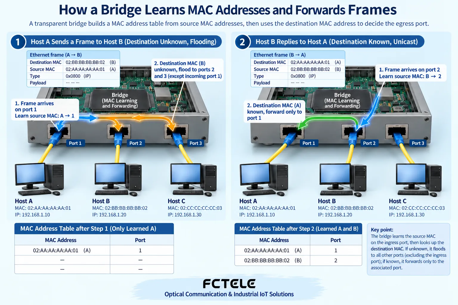
Transparent bridging is common in Ethernet. Suppose device A sends a frame to B from port one. The bridge first sees the source address A, so it knows that A can recently be reached from port one, and writes this correspondence into the address table. Then it looks up the location of destination address B. Learning the source address and looking up the destination address are two consecutive but different actions. The address table cannot be understood as all communication routes manually filled in by applications.
If B has not yet been learned, the bridge may send this unknown unicast to other ports within the VLAN scope that meet forwarding conditions, and not send it back again from the original incoming port. When B replies, the bridge learns the port where B is located from the source address of the reply frame. Later, when A sends to B again, it can usually directly choose the corresponding exit, reducing unnecessary flooding. Specific filtering and forwarding are still constrained by device functions and configuration.
The address table changes; it is not a permanent map
Devices may lose power, move, or change access locations, so the dynamic address table needs updating and aging. Aging can be understood as old location records gradually becoming invalid without continuous evidence, rather than saving all historical device locations. Learning refresh is usually related to observed source addresses. It cannot be said that as long as someone else sends a frame to B, it can be determined that B is still on the original port.
When a record does not exist, frames with unknown destinations may be flooded again. This does not mean the bridge is broken, nor does it mean it will permanently broadcast all frames. In practice, administrators also need to consider functions such as static addresses, port security, and VLANs. If the MAC location of a device repeatedly changes between two ports, check the wiring, topology, and possible loops, rather than only staring at the instantaneous result in a certain table.
Why an extra cable may cause a Layer 2 loop
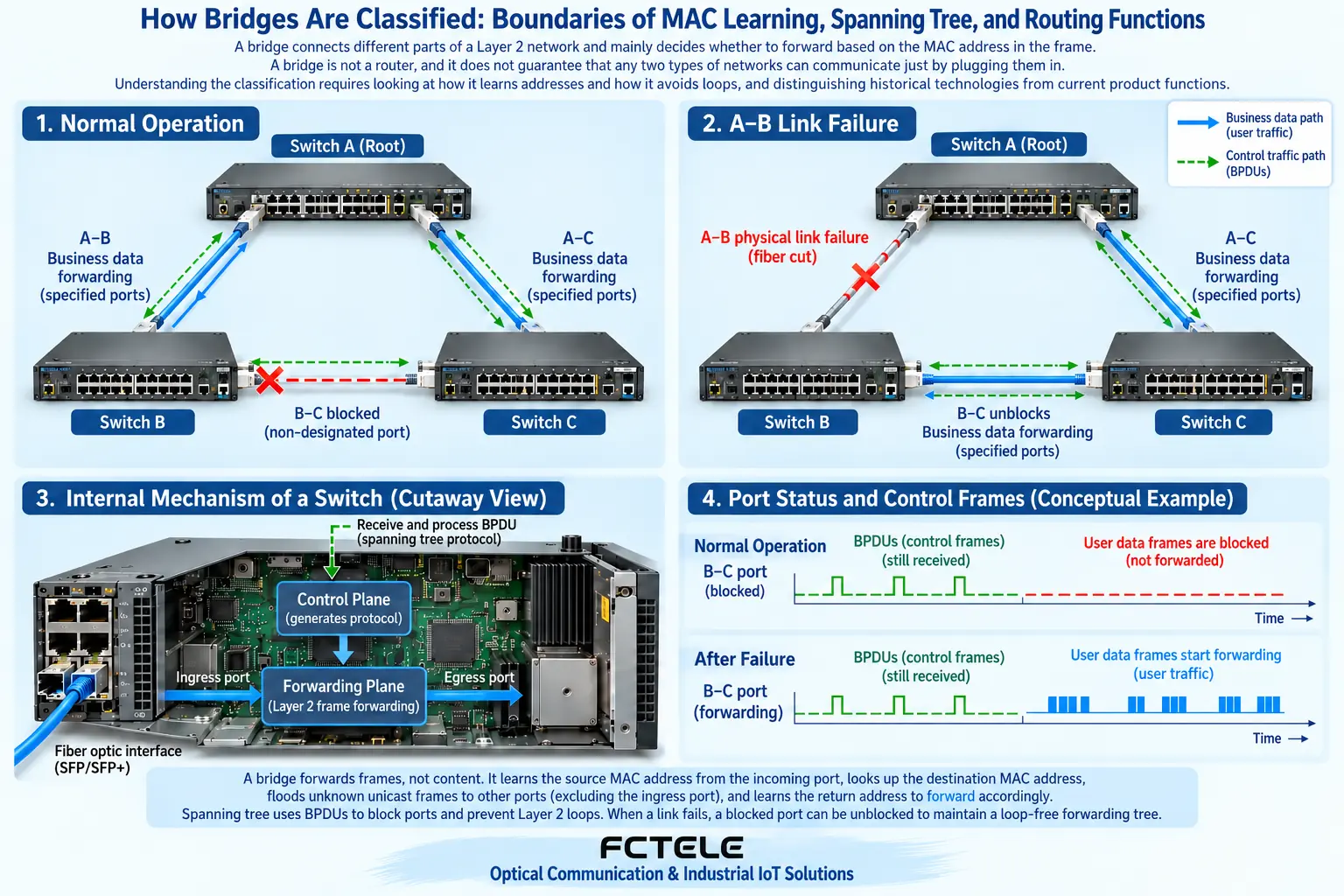
A backup line connecting two areas seems to improve reliability, but in ordinary Layer 2 forwarding, Ethernet frames do not rely on a hop-by-hop decreasing TTL like IP packets to control loops. Broadcasts or unknown unicasts encountering multiple forwarding paths may be propagated repeatedly; multiple copies are then forwarded further, which may fill links and affect address learning. Physically forming a circle does not equal automatically obtaining a safe backup.
This is also why spanning tree mechanisms appeared. They let bridge devices that support the corresponding protocols exchange control information and select a set of paths that will not form a service forwarding loop. Some redundant ports restrict ordinary service forwarding, but the actual cable is still connected, and workers do not need to unplug the backup line. Whether the backup path can be correctly enabled after a fault depends on the protocol, configuration, and the entire topology.
The root of spanning tree is not simply selected by factory serial number
Spanning tree compares information such as bridge identifiers. A bridge identifier involves components such as priority and MAC address, and specifics also depend on the protocol mode used. It cannot be written as “broadcast the manufacturer serial number, and the smallest becomes the root.” Administrators can plan the root location through the corresponding mechanism, but this is specific configuration work and should refer to the model and firmware manual, not apply one universal command.
Other devices choose port roles based on the path cost to the root and necessary comparison rules. The purpose of learning these terms is to understand why a certain physical link does not carry ordinary service, not to memorize a set of fixed port numbers. Mechanisms such as STP and RSTP have different states and convergence processes, and private ring protocols cannot be equated with them just by name. Fast recovery even more cannot be assumed by default to mean zero application interruption.
Historical source route bridges and modern IP routing are not the same thing
Older materials may also list transparent bridges and source route bridges side by side. Source route bridging is related to historical Token Ring networks, and the sender participates in specifying the bridging path and other processes. This type of classification can help understand the evolution of network technology, but it should not be copied as the two product types of all today’s industrial switches. When purchasing equipment, you should read the currently supported Ethernet bridging, management, and redundancy functions.
The “source route” in it also cannot be directly interpreted as today’s router forwarding across subnets based on IP addresses, or as equivalent to the wireless radio frequency transmission of a wireless bridge. Bridging method, transmission medium, and network layer functions are different dimensions. A wireless device may connect two areas in bridging mode, but it still needs separate verification of frequency band, distance, interference, and security settings. These capabilities cannot be inferred from the word “bridge.”
How to distinguish bridges, switches, and routers
A multi-port Ethernet switch often performs bridging tasks and forwards according to MAC addresses within the relevant Layer 2 scope. Routing functions mainly handle how different IP networks are reached. Some switches support Layer 3 functions, but whether they support them and to what extent depends on the specific model and configuration. If a product says it is managed, that does not automatically prove it can perform all routing functions.
A simple way to judge is to first write down the requirement clearly: is it only extending the same Layer 2 network to another location, or is it necessary to let different subnets communicate, restrict access, or connect to a WAN? The first type of problem can start with bridging and medium transmission; the second type also requires checking routing and security design. Optical ports, wireless interfaces, or industrial enclosures only describe some product features and are not enough to answer all requirements.
Feichang Technology product selection should look at specific supported mechanisms
The managed industrial switch product details on the Feichang Technology official website, for example the related mini two-fiber four-copper model, list management and redundancy functions such as STP/RSTP. It can serve as a candidate for evaluating controlled redundant Ethernet, but it is not evidence that all Feichang Technology devices support the same protocol, the same state, or the same recovery behavior. Specific versions should also be checked against delivery materials, and compatibility should be verified with other participating devices.
Unmanaged devices cannot be assumed to handle any closed-loop topology just because they also have two optical ports. When a backup path is truly needed, the physical connections, protocol-participating devices, normal blocking locations, and post-fault paths should be drawn clearly. The number of uplink ports, optical module matching, power supply, and on-site environment should also be checked separately, to avoid using one kind of “bridge classification” to cover up actual engineering requirements.
Use fault testing to prove whether the backup path is effective
Within an authorized maintenance window, you can record port roles, service paths, and application performance in a healthy state, then simulate a planned link fault and observe the forwarding path and service recovery. The test object should include real applications, not just watching a light turn green. After testing, restore the original connections and check the network state, and keep logs and change records so that you can judge whether later anomalies are related to this operation.
Do not casually connect a closed loop for testing in a production network, and do not disable existing loop protection just to make the backup line “connect immediately.” For beginners, the most important conclusion is: address learning determines which exit to use, mechanisms such as spanning tree determine which exits are currently allowed to forward, and routing is responsible for problems at another layer. Only by distinguishing these three things will you avoid treating one more line, one more optical port, or a product name as a complete solution.
Verification materials:Ethernet bridging principles;Spanning tree and RSTP;Feichang Technology managed industrial switches. The diagram explains general mechanisms and is not a wiring diagram for a specific model.
Translated from the Chinese technical article. Source first published: 2019-10-22. Source last revised: 2026-10-13T20:54:09+08:00. Read the Chinese source
