


First ask whether it forwards bit states or receives complete messages
Both CAN repeaters and CAN bridges can connect two network segments, but they connect in different ways. A physical repeater extends or regenerates bus states, while a bridge usually receives a complete message on one side and then sends it to the other side according to rules. Procurement cannot just look at the words “transparent” and “repeater”: you should ask the manufacturer to explain the processing layer, the rates on both sides, where acknowledgment occurs, the forwarding direction, and fault behavior, then judge whether it meets the communication needs of the original system.
You can think of the former as a voice path that extends a conversation, and the latter as listening to a full sentence first and then repeating it in another room; this analogy only explains the processing order and cannot calculate delay or prove that a message will definitely arrive. A bridge storing a message does not necessarily change the application data, but it may change when messages arrive, queuing, and the scope of error feedback. Even if the content looks the same, system behavior can still differ.
Transparent repeaters still have to respect CAN arbitration timing
A CAN node also reads the bus while transmitting. During arbitration, a node that sends a recessive bit but reads a dominant bit withdraws from this competition, letting the higher-priority message continue. This process requires the node to see the relevant state within a specified time, and cable propagation, transceivers, and repeater processing all take time. Therefore, regenerating waveforms can improve the electrical connection, but it cannot let the timing budget grow without limit.
Fiber repeaters reduce conductive connections and electromagnetic coupling in the middle segment, but light still needs propagation time, and devices may also introduce processing delay. Whether the original rate can be kept at the target distance depends on the specific mechanism and full-system verification. Electrical isolation, optical transmission, and protocol bridging are different features, and any one of them cannot independently prove another capability. Classic CAN and CAN FD, and upper-layer CANopen or J1939, should also be checked separately; do not assume compatibility just because the interfaces are all called CAN.
A bridge turns one contention domain into two contention domains
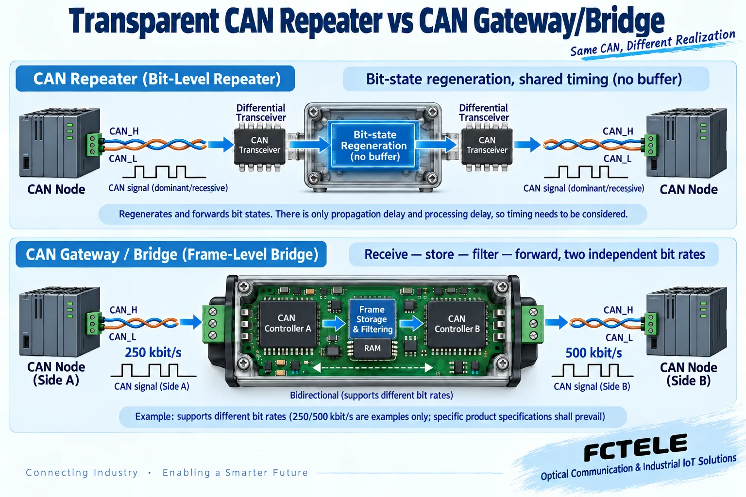
A typical message bridge has two CAN controllers: port A participates in communication on segment A, and port B participates in communication on segment B. After segment A receives a valid frame, the bridge can participate in acknowledgment on this segment, then place the message into an internal buffer; after port B gets a chance to transmit, it sends the message again and accepts acknowledgment and error handling on segment B. The two sides arbitrate separately, and the original priority relationship on side A does not automatically determine that the message will be sent immediately on side B.
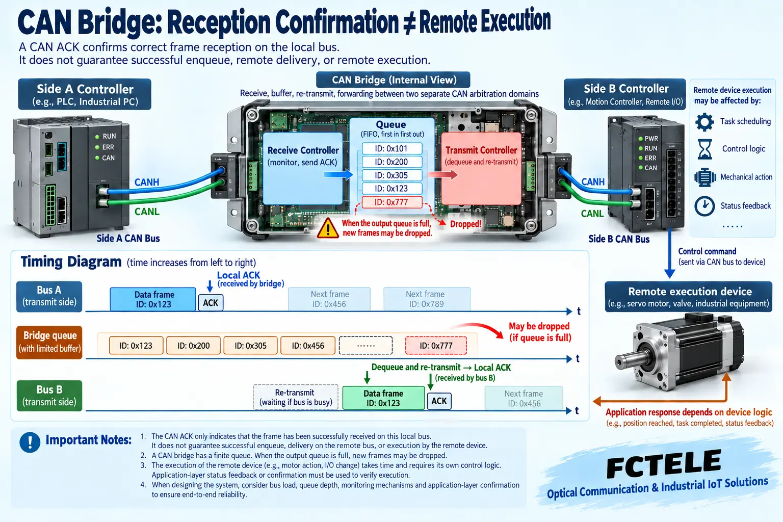
If the receiving port acknowledges on its own segment, successful transmission on side A only proves that a node on this segment correctly received the frame; it does not prove that side B has received it, and even less that a remote actuator has completed an action. Important commands need suitable application responses, sequence numbers, timeouts, and fault strategies; these belong to system protocol design and cannot be replaced by a link light. You must confirm with the manufacturer how ACK is handled and how forwarding failure is reported, because not every product provides the same visible status.
Different rates can be bridged, but buffering cannot create capacity
A complete-frame retransmission mechanism can provide the conditions for setting the rates on the two sides independently. For example, segment A at 250 kbit/s and segment B at 500 kbit/s is an example that requires explicit product support and is not a wiring method for all repeaters. Each side must also match the rate and bit timing of its nodes. A transparent bit-state repeater cannot directly treat two networks with arbitrary different rates as one continuous bus.
If the effective traffic continuously generated on the faster side exceeds what the slower outlet can send, the waiting queue will grow, and limited buffering may eventually overflow. When calculating load, you cannot count only data-field bytes; you must also consider identifiers, protocol overhead, bit stuffing, retransmissions, and competition. Buffering is suitable for absorbing short bursts and cannot guarantee lossless delivery for any continuous input. Acceptance should observe drop counters, queuing time, and application timeouts, not just whether one frame can be transmitted when idle.
ID filtering and bidirectional forwarding need clear rules
CAN identifiers are used for arbitration and often participate in application message identification; they are not equivalent to Ethernet destination addresses. A bridge can decide whether to forward based on conditions such as ID, standard or extended frame format, and direction, and the specific rules depend on the model. Selective forwarding can reduce irrelevant traffic, but mistakenly filtering heartbeat, management, or fault messages can also make the system appear online while failing to operate normally. You should verify item by item against the complete list of application messages.
When establishing a bidirectional connection, confirm whether the device prevents the same frame from being forwarded back and forth, and what happens after multiple bridges form a closed path. An ordinary CAN bridge does not automatically have an Ethernet spanning-tree mechanism, and you cannot connect it into a ring arbitrarily and expect duplicate messages to be eliminated. Start with a simple topology that has a basis, and when necessary specify the forwarding direction and filtering policy; more complex redundant structures can only be designed according to the corresponding product documentation. Filtering is also not equal to identity authentication or encryption, and security capabilities require separate evidence.
Verify termination, isolation, and fault scope separately
When the two sides of a bridge are independent electrical segments, each segment needs correct wiring order, trunk, drop line, and termination design. Whether the two segments are electrically isolated, what the isolation rating corresponds to, and how reference ground and shielding are handled should be checked in the specific hardware documentation. Do not infer two isolated paths just because the chassis has two terminals, and do not treat an isolation value as a guarantee that the whole device can withstand any lightning strike.
After an error or bus-off occurs on one side, the other side may still be able to communicate, but some applications will fail because cross-segment messages are interrupted. Fault isolation is only one mechanism for limiting the spread of impact and cannot replace the application safe state. The system should specify how long without a message update triggers an alarm, how old buffered data is handled, and whether resynchronization occurs after recovery. Writing these requirements clearly during design is more effective than only asking afterward, “Why is the light normal?”
Use representative messages to verify actual bridging effect
First build a small number of nodes on each side, check frame format and direction, then test filtered and non-filtered messages, different rates, and continuous load. Record input, output, delay, drops, and application response, and do not directly subtract timestamps from two different interfaces while ignoring clock synchronization. If multiple tools are used, the measurement basis and accuracy need to be stated; the queue and timeline in the figures are only general mechanism illustrations.
Then add real nodes and periodic tasks, and check priority competition, burst input, and whether low-priority messages time out under high load. In a maintenance window, simulate one side being disconnected or offline, and verify message backlog, alarms, and recovery strategy. A bridge that can send and receive on a bench does not automatically satisfy motion control, traffic control, or other safety-critical scenarios; applicability is determined by project agreements and full verification.
Find the corresponding product object according to business needs
If CAN transmission supported by the devices needs to be maintained between two cabinets, first check a CAN fiber optic modem; if two independent CAN networks need different rates or selective forwarding, check equipment that explicitly has frame bridging; if instrument objects need to be converted into another industrial application protocol, consider a gateway with a mapping definition. They may share similar interfaces, but the tasks they undertake are different.
Feichang Technology’s CAN bus fiber optic modem category provides product entries with different channels and optical directions; when selecting, check the corresponding model to confirm topology and transmission mechanism. The category page contains optical extension products, which does not prove that any model supports ID filtering, rate bridging, or CAN FD. The procurement record should at least include the specific version, network conditions on both sides, forwarding rules, buffering and exception descriptions, acceptance baseline, and maintenance method, to avoid replacing formal delivery documents with a set of general specifications that have no model source.
Documentation note: The principle diagrams have been checked against technical content and are used to explain general mechanisms; they are not product photos or measured records. Specific interfaces, modes, and capabilities are subject to the selected model, version, and on-site verification.
Verification materials: TI: CAN physical layer and wiring requirements
TI: TCAN1042 transceiver documentation
Feichang Technology CAN bus fiber optic modem category
Translated from the Chinese technical article. Source first published: 2020-08-31. Source last revised: 2026-10-13T13:46:37+08:00. Read the Chinese source
