


Even when both use E1, asynchronous serial ports and synchronous interfaces cannot be bought interchangeably.
When old equipment only has an RS232 or V.35 interface, but the cross-site resource is a single E1 circuit, a corresponding interface converter can carry the data. Both ends still face the original service interface, with E1 acting as the middle channel. The converter is not responsible for automatically parsing arbitrary industrial protocols, and it does not turn every service into Ethernet just because it has a serial port.
The name RS232 first describes an electrical interface; you cannot judge from the name alone that a given port must be asynchronous. Common terminals use asynchronous characters, while some telecommunications equipment provides a synchronous serial interface with a clock. V.35 generally targets synchronous data. Before deciding on a model, first read the terminal manual and list whether it is asynchronous or synchronous, the rate, control signals, pins, and clock requirements. Do not decide the wiring only from the DB9 or DB25 shape.
How asynchronous characters enter a continuously running E1 line
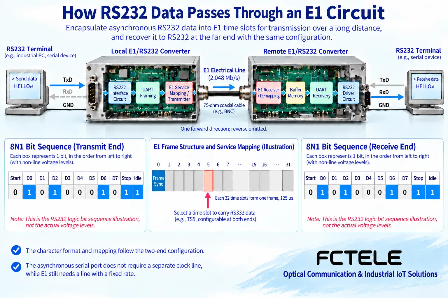
Common asynchronous RS232 sends one character at a time, using a start bit, data bits, and stop bits to help the receiver identify character positions, and it may include a parity bit. The terminal and receiver need to match rate and character format, and there is usually no separate clock line. Data may appear intermittently, but the E1 line still runs at its own continuous pace, and the two paces are not the same.
One common implementation first receives the serial level, then through character processing or a corresponding encoding mechanism, temporarily stores the data and maps it to the E1 service position agreed by both sides; the far end extracts it and restores the serial output. Specific devices may use different encoding methods, and you cannot assume every product has the same UART structure or per-character encapsulation. Both sides must support the same bearer mechanism to correctly restore the data relationship.
Buffering only absorbs limited bursts. If the application continuously sends data exceeding the bearer or port processing capability, waiting, loss, or flow-control actions will still occur. The serial baud rate, the E1 bus rate, and the effective application throughput are also different: start and stop bits in characters, protocol messages, and service mapping can all consume capacity. You cannot write 2.048 Mbit/s as the net data rate obtainable by any serial terminal.
Data may arrive, but handshake status may also determine whether sending is possible
Some terminals use only transmit, receive, and a common reference, while others also rely on control or status lines such as RTS, CTS, DTR, and DSR. If only data is forwarded without satisfying the handshake conditions the terminal needs, the result may be that one end never sends, connection setup fails, or intermittent pauses occur. Do not use arbitrary shorting to hide unknown interface requirements; first confirm the cables and handshake mode on both sides.
The Feichang Technology FCC-E1R1 details provide one E1 and one RS232 data bearer, while the FCC-E1qR1 details explicitly list E1 remote transmission of RS232 handshake signals. The latter helps terminals that need control status maintained across sites, but this does not mean all serial converters should be called “full-signal.” This is a specific selection difference and should be determined by which signals the terminal actually uses.
The above official website details have different statements of the serial rate range among the summary, features, and parameter tables, and some content also mixes in other serial interfaces. This article does not promise a unified maximum rate, electrical protection, or temperature range based on that; you should obtain clear rate, port, and wiring information for the ordered version, and confirm compatibility of paired devices before acceptance.
V.35 synchronous data: why do you still need to care about the clock?
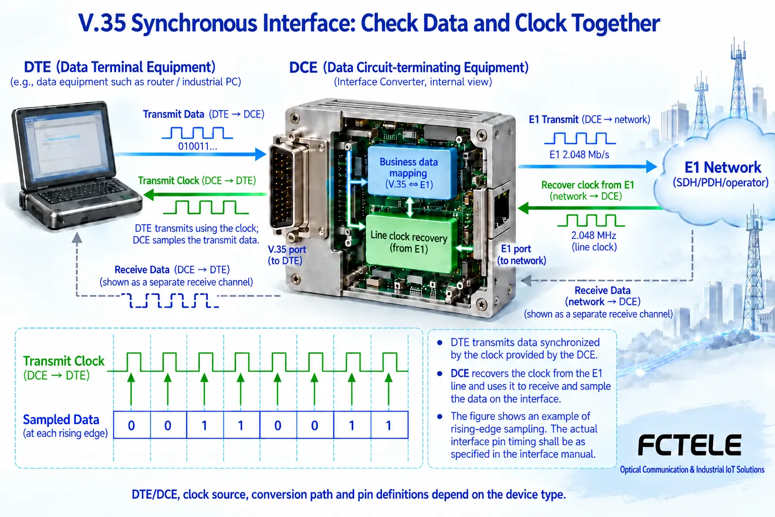
Synchronous data reception reads data according to the agreed clock edge, rather than adding start and stop bits to each character. In addition to the data direction, you also need to confirm who provides the transmit and receive clocks and which end uses them. DTE is the data terminal role, and DCE is the role that connects to the communication circuit; the role names help explain the port relationship, but they cannot replace the specific clock line and control line definitions.
For example, the converter acting as the DCE role recovers a reference from the E1 side and provides the corresponding transmit clock to the DTE, and the DTE sends data at that pace; this is one possible configuration. The site may also use a terminal or external reference. Do not specify that all devices must use the same DIP switch position, and even less should both ends wait for a clock that has no source. Draw out the reference source and data path for each end separately.
The Feichang Technology E1 to V.35/V.24 series distinguishes framed and unframed versions. The FCC-E1fV1 details correspond to framed E1 and V.35 adaptation, involving the selected service timeslots; unframed products target data for the entire corresponding line. Adapter cables from DB25 to other interfaces must match the product definition, and the plug shape cannot be taken as proof of V.35 electrical or clock compatibility.
Framing, timeslots, and line timing must correspond item by item
Framed E1 divides one frame into thirty-two eight-bit timeslots, with eight thousand frames per second. TS0 carries overhead such as frame alignment, and the use of TS16 depends on the service mode, so the available data timeslots cannot be calculated only from the total number on the panel. The service rate of a synchronous interface may be a combination of selected sixty-four kilobit channels, and the specific range is determined by the product mode.
The framing method, CRC, timeslot mapping, and circuit connection of the intermediate transport network at both ends should correspond. The fact that serial data can pass through a short local cable does not prove that the cross-site circuit has been delivered to the correct timeslot. E1 seventy-five ohm and one hundred twenty ohm interfaces also require corresponding cables and impedance conditions, and you cannot connect a network patch cord directly to unchecked E1 pins.
“Asynchronous serial port” does not mean the entire system does not need a clock. The serial port may not use a separate clock line, but the E1 carrying it still needs line timing; circuit emulation over IP also has the issue of output clock recovery. The object described by synchronous and asynchronous should be stated clearly, otherwise character interfaces, network messages, and E1 frequency will be mixed into the same thing.
First do one service, then expand to the site
Save the configuration during the maintenance window, and first have the paired devices test against each other in a short-link test environment. For asynchronous services, check the rate, data bits, parity, stop bits, and handshake, and verify bidirectional transmission separately; for synchronous services, check the DTE/DCE roles, clock source, and sampling relationship. Tests should use only the wiring and power allowed by the manual, and do not try connections on unknown interfaces.
After the short link passes, connect it to the formal E1 circuit and observe loss of signal, loss of frame alignment, bit errors, and application response. Test both small messages and actual burst and continuous loads, and record whether bytes are lost, whether the order is correct, and whether handshake status changes. When loopback or test codes are needed, first clarify the interruption scope; at the end, you must exit the test state and restore the real service.
What is chosen is the bearer method, not general protocol translation capability
Suppose the remote instrument outputs asynchronous RS232 and the local system still needs the same serial data; you can evaluate a paired serial-to-E1 setup. If the terminal provides a V.35 synchronous interface, then you move to selection of synchronous interface and timeslot adaptation. If the middle only has optical fiber or IP, you should recheck the complete bearer plan, rather than assuming by default that an E1 converter can directly connect to any optical port or network.
Transparent transmission lets the far end obtain the corresponding data, but it does not automatically change the application protocol, device address, or master-slave relationship. Only by settling the service interface, E1 channel, control signals, and timing separately is it easy to explain why it is connected this way, how capacity is limited, and what test proves that the equipment truly meets the need.
Data note: The principle diagrams have been checked against technical content and are used to explain general mechanisms; they are not product photos or measured records. Specific interfaces, modes, and capabilities are subject to the selected model, version, and on-site verification.
Reference materials: ITU-T G.703: Electrical characteristics of digital interfaces
ITU-T G.704: E1 and T1 frame structures
Feichang Technology E1 to serial interface series
Feichang Technology FCC-E1R1 serial bearer device
Feichang Technology FCC-E1qR1 full-signal RS232 to E1
Feichang Technology E1 to V.35/V.24 series
Feichang Technology FCC-E1fV1 framed E1-V.35 converter
E1 converter classification and selection
Translated from the Chinese technical article. Source first published: 2020-04-07. Source last revised: 2026-10-13T13:46:37+08:00. Read the Chinese source
