


FCTEL / NETWORKING & CONFIGURATION
Verify protocol conversion first; then align serial settings, unit IDs and the TCP path.
An Ethernet socket carrying raw serial bytes is not automatically a Modbus TCP server. Select a model and operating mode that explicitly supports RTU-to-TCP conversion, then prove the path with a known register on one slave before adding the rest of the bus.
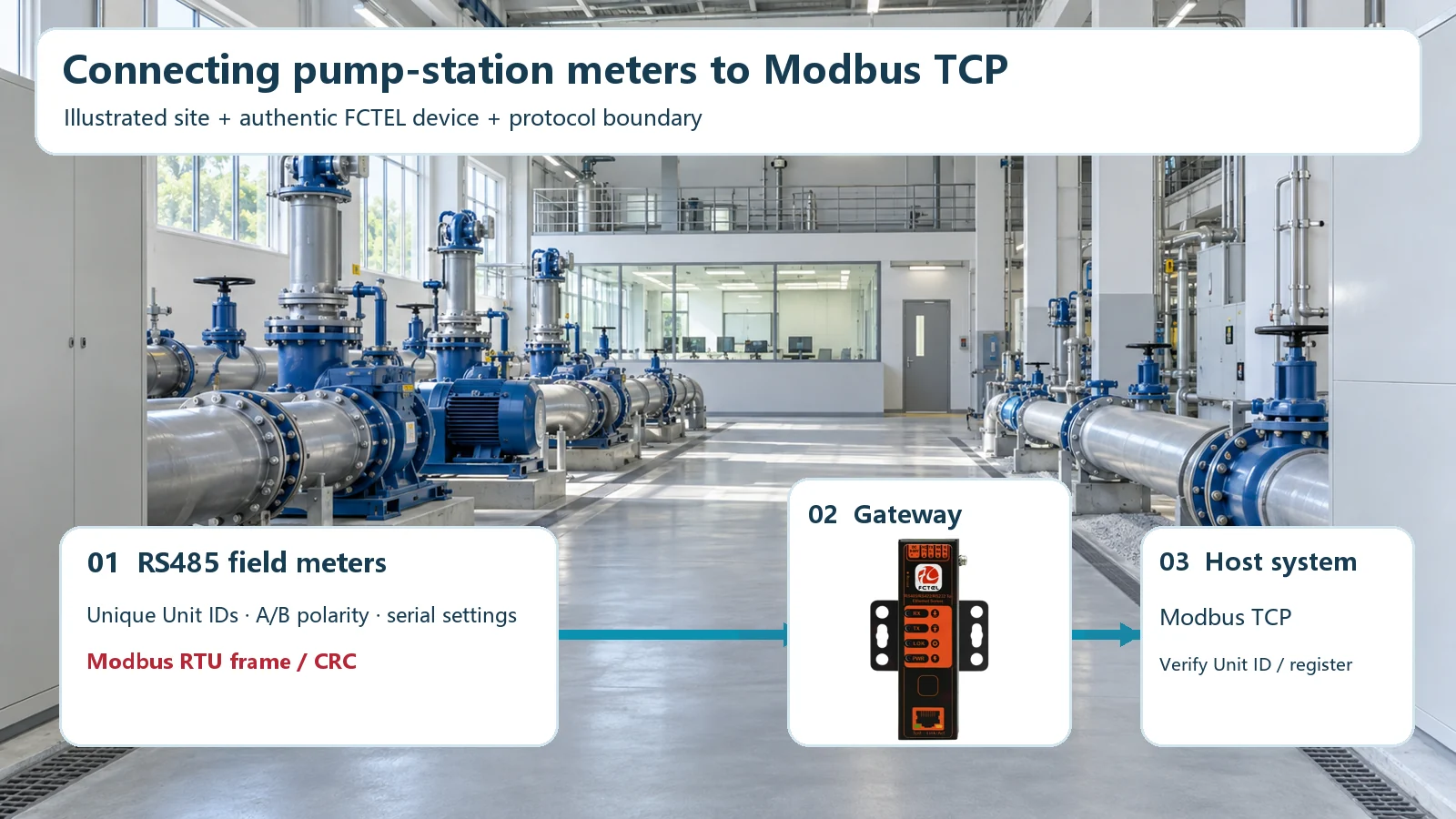
01Decide whether you need a gateway or a serial tunnel
A common plant architecture has an Ethernet SCADA system, a serial server near a pump or production line, and several RS485 instruments on a shared cable. The host wants to issue Modbus TCP requests. The instruments understand Modbus RTU frames. Although both use familiar Modbus function codes and register concepts, their transport envelopes differ: Modbus TCP includes an MBAP header, while RTU serial frames include timing rules and a CRC. A simple TCP-to-serial byte tunnel does not necessarily translate one envelope into the other.
Begin with a written question: must a standard Modbus TCP client communicate directly with RTU slaves, or will the client itself construct RTU frames inside a TCP stream? The first use case calls for an explicit protocol-conversion or gateway function. The second can sometimes use a transparent serial tunnel, but the client software must know what it is receiving. Confusing these modes is a frequent reason for a healthy Ethernet link and a completely silent application.
The official FCTEL FCT-081219 product page describes a selectable RS485/RS422/RS232 serial interface and an RTU-to-Modbus-TCP application direction. It is a useful product-specific starting point, not proof that every FCTEL serial server or every firmware version offers identical settings. Obtain the current manual and confirm the precise interface, conversion mode, addressing behavior, power supply and installation limits for the unit being delivered.
02Draw the electrical and Ethernet boundaries
Before opening a configuration page, sketch the field route. Mark each instrument’s physical location and Modbus unit address, each junction, the RS485 trunk, short drops and the two electrical endpoints. A two-wire half-duplex segment normally follows a continuous trunk. Check the equipment’s A/B convention rather than trusting that two manufacturers use the same letter polarity. Record signal reference, shielding and the site’s grounding design. Place end termination according to the cable’s differential impedance and the device’s built-in switch settings; do not scatter resistors along intermediate nodes.
Termination reduces reflections; biasing gives a defined idle state where the transceivers require it. They are different networks and neither fixes a wrong serial format or a duplicate unit ID. For the physical principle and commissioning checks, see our RS485 termination guide. If the installation spans buildings, crosses ground-potential boundaries or has an unavoidable star layout, reconsider the physical architecture rather than hoping the gateway will conceal wiring faults.
On the Ethernet side, record the server IP address, subnet, gateway, listening port, host IP and any VLAN or firewall boundary. A successful ping only proves one kind of IP reachability at that moment. It does not prove that a TCP service is listening, that the server is in the intended conversion mode or that an RTU slave responds to the mapped unit ID. These layers need separate evidence during acceptance.
03Match the serial format, then verify the register
Read the instrument documentation or a known-good configuration export. Record baud rate, data bits, parity and stop bits, and apply the same values to the server’s serial port. A conventional single-port RS485 master cannot reliably poll devices that expect incompatible serial formats on the same electrical segment. Standardize the instruments or divide the network into separately configured ports or segments. Do not assume that a generic automatic-detection option can guess every combination.
Assign each RTU slave a unique unit ID on that bus. Prepare a test request that is documented to work on one instrument: the function code, starting register, quantity, access rights and expected data type. Register notation is another trap. Some manuals describe a protocol offset beginning at zero; operator-facing lists may print a 4xxxx holding-register number. Check how the client library wants the address expressed. A one-register offset or an unsupported function can return an exception even when electrical communication is flawless.
Test this request directly on the serial side with a known-good master, if practical. Save the raw request and response before inserting the Ethernet bridge. It gives the commissioning team a control sample and prevents a device-specific register issue from being misdiagnosed as a TCP problem.
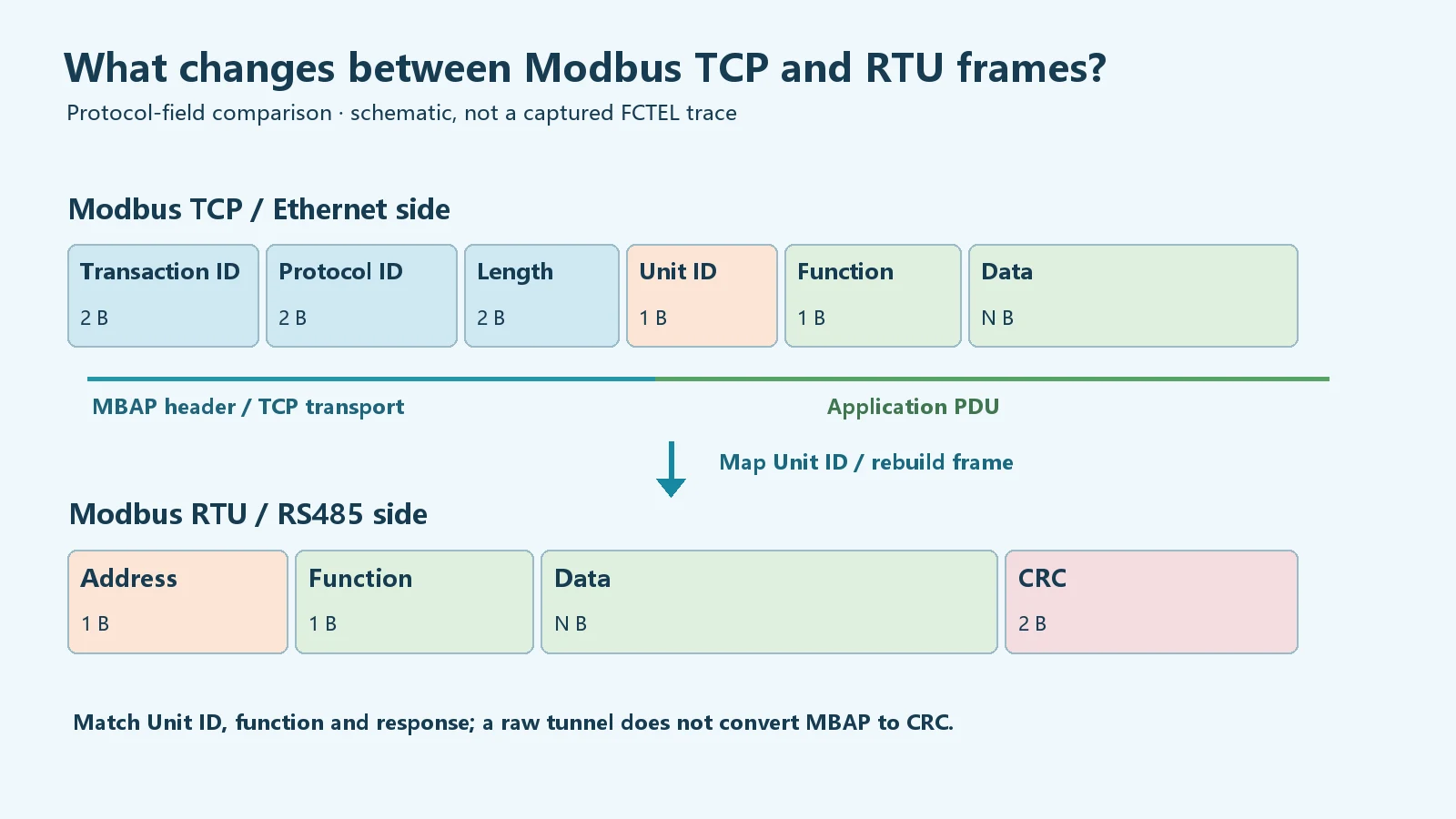
04Configure the mode and unit-ID handling
Work first on an isolated maintenance network and back up the device’s existing configuration and firmware identification. Follow the exact manual to choose the operating mode that supports RTU/TCP conversion. Enter the management address and network settings, define the service endpoint required by the application, save the settings and restart the relevant service if the model requests it. Avoid assuming that every serial server uses the same default port or that a displayed “TCP server” label necessarily means a Modbus TCP protocol server.
In conversion mode, check how the TCP request’s Unit ID reaches the RS485 line. One implementation may pass it through, another may use a fixed slave ID, and another may maintain a mapping table. The host and field-device documentation must agree on the effective address. Confirm this with a TCP capture and, where available, a serial trace. A request that reaches the correct IP but emerges with the wrong RTU address will never receive the intended instrument response.
One half-duplex bus can carry only a limited sequence of requests at a time. If several hosts poll the same server, ask how the model queues or arbitrates requests and verify the resulting scan cycle under real load. Timeouts should cover the field device’s documented response behavior but should not be increased indefinitely to hide a failing cable. Keep the initial test deliberately simple: one TCP client, one RTU slave, one known register.
05Commission one slave, then the whole site
Start with the known-good instrument. Confirm that the TCP session opens; send the test read; correlate the TCP request with serial transmission, RTU reply and returned value. Record timestamps, unit ID, function code and exception codes. If TCP connects but the serial transmitter never sends, revisit mode and address mapping. If the port transmits but nothing answers, inspect power, A/B polarity, the unit ID and the serial format. If the instrument returns a Modbus exception, look at function and register validity before changing physical termination.
Add the remaining slaves one at a time. Repeat the same read at the most distant node and while normal plant machinery is operating. Watch retries, frame or CRC errors, application timeouts and the value trend. Duplicate unit IDs can make a small network appear intermittent; long stubs, incorrect termination and loose terminals often affect remote nodes first. Save a clear drawing of the final physical route and switch positions, not merely a list of IP addresses.
Plan controlled recovery tests in an approved maintenance window. Disconnect an uplink, interrupt one field device, and restart the server in turn. Check the alarm, stale-data behavior, reconnection and return to normal polling. A system that reads correctly once but fails to recover after a routine restart has not passed acceptance. Log the topology version, model, firmware, configuration backup, representative packets and recovery result so the next technician can reproduce the evidence.
06Troubleshoot by layer instead of swapping parts
| Observed symptom | First checks | Evidence to keep |
|---|---|---|
| No TCP connection | IP address, subnet, port, firewall and service state | Host connection attempt and device network configuration |
| TCP connected, no serial frames | Operating mode, mapping and request format | TCP capture and serial transmit indication |
| Frames sent, no slave reply | Instrument power, A/B polarity, serial format and unit ID | Raw serial request, endpoint drawing and switch positions |
| Response present, value wrong | Register offset, data type, scaling and byte order | Raw response and the instrument register table |
Keep electrical, transport and application findings separate. Replacing an industrial switch will not fix a wrong holding-register offset. Adding a line terminator will not cause a transparent tunnel to translate MBAP into RTU. Conversely, changing a server setting will not cure a severely branched RS485 cable. Each corrective action should follow a recorded observation and be re-tested under the same conditions.
07Select the product for the actual boundary
The FCT-081219 page establishes a real FCTEL serial-server product direction, and its official product image is used in the application illustration above. Verify the exact terminal assignments, electrical isolation, supply range, firmware function, supported connection roles and environmental specifications against current documents for the ordered model. A single-port device should not be extrapolated into a multi-segment gateway. If the project requires multiple isolated serial buses, long fiber spans or cross-building routing, choose and validate a corresponding architecture instead of stretching a product category beyond its published scope.
In the final handover, provide the network diagram, unit-ID register map, device configuration, test traffic and rollback procedure. These artifacts make future instrument replacements and firmware changes safer. The useful outcome is not a green Ethernet LED; it is a repeatable, documented path from the TCP client’s request to the intended RTU slave’s response and back.
For product details, consult the official FCT-081219 specification page (Chinese). For a related physical-layer question, see where RS485 termination resistors belong. Final parameter values and commissioning decisions must follow the equipment manual and the conditions of the installed cable and instruments.
