


After traveling a long distance, an optical signal becomes weaker and may also suffer pulse spreading and timing shifts. A receiver can amplify weak electrical signals and make decisions; suitably designed equipment can recover clock timing and retime data too. These processes do not mean every ordinary Gigabit converter contains an optical amplifier, or that unreadable data can be repaired from nothing. Distinguishing receiver amplification, optical amplification and regeneration helps determine how to extend a long-distance link.
1. How light becomes electricity again
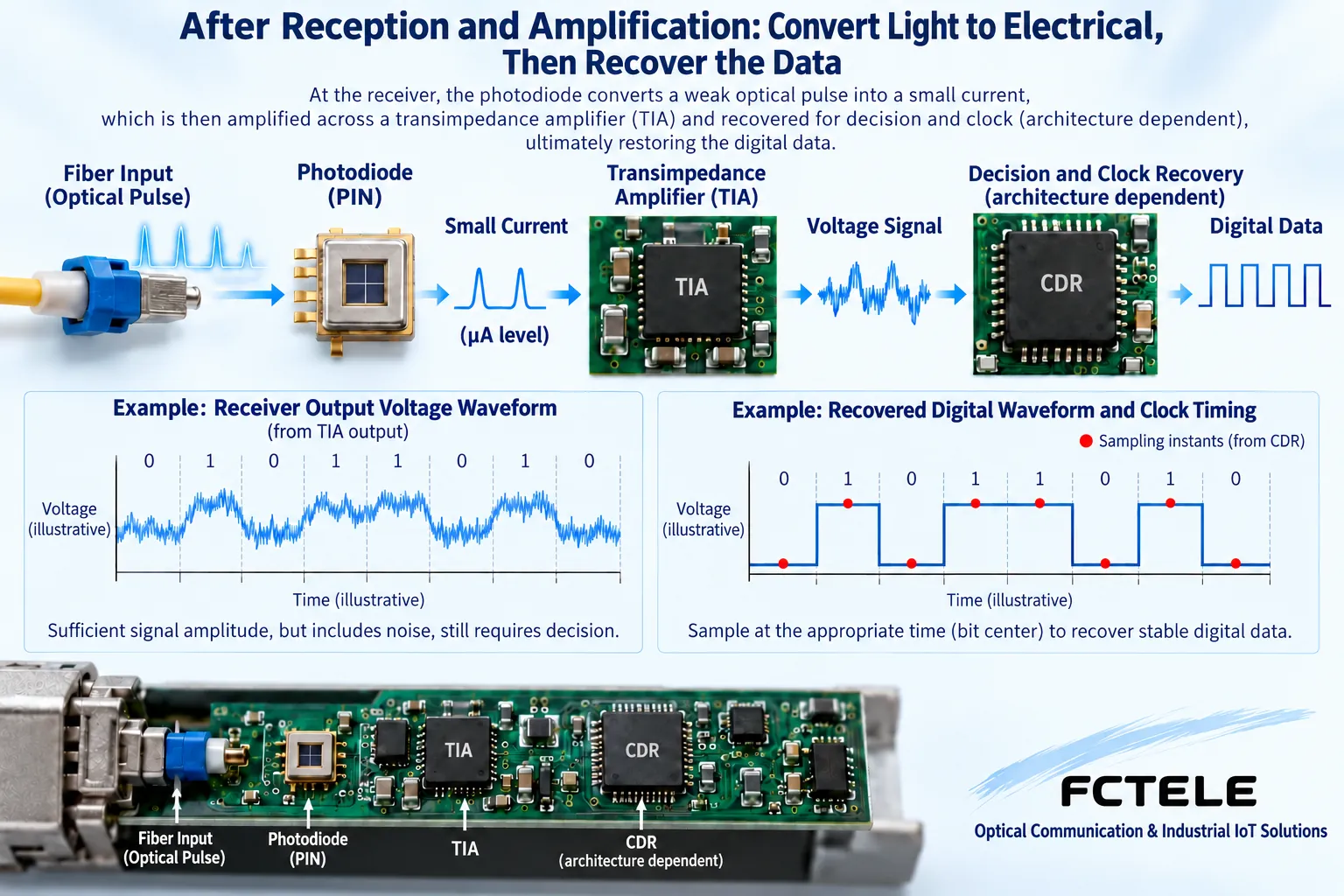
At the transmitter, data changes become optical signals that travel through fiber to the receiving photodiode. The photodiode converts incident light into a small current. A transimpedance amplifier then converts that current into a usable voltage signal. It is also commonly called a receiver preamplifier. What it amplifies is already an electrical signal; it does not directly strengthen light inside the fiber.
Subsequent amplification, limiting and decision circuits turn the received signal into digital data within specified input conditions. A decision determines the logical state of a bit from its input at a particular instant. Noise, bandwidth, sensitivity and overload constrain this process: a little remaining light does not guarantee recovery. Receiver amplifiers can introduce noise and distortion too, so more gain does not necessarily improve communication quality.
2. Why adequate optical power may still yield incorrect decisions
Attenuation mainly weakens arriving light. Dispersion spreads pulses, making neighboring bit boundaries harder to distinguish. Noise causes amplitude fluctuations, while timing jitter shifts edges in time. These are different problems. A power meter measures power; it does not directly reveal whether every bit has enough decision margin. A normal reading cannot replace bit-error, link-error or real-service acceptance tests.
Think of reception as reading numbers at the right instant: faint writing resembles an amplitude problem, overlapping writing resembles waveform distortion, and reading at the wrong time resembles a timing problem. This analogy only separates the concepts; it cannot calculate bandwidth or distance. Actual behavior depends on interface coding, circuit design and specified test conditions. An analogy cannot prove that equipment repairs every kind of distortion.
3. How clock recovery helps retime data
A clock and data recovery circuit extracts appropriate sampling timing from received signal transitions, then decides or retimes the data. The clock determines when to sample, while data recovery determines the output logical state. More regular output bit boundaries can improve subsequent processing, provided the input remains within the circuit lock and decision ranges. Weak signals, excessive distortion or a rate mismatch can cause loss of lock or incorrect decisions.
Not every fiber media converter uses the same separate clock-recovery chip. A PHY or another integrated circuit may incorporate the function, while some modules perform only certain analog processing. Analog Devices documentation shows that this receiver mechanism exists; it does not prove every FCTEL model uses that component. Ask about complete-device behavior rather than turning every chip feature into a product promise.
4. Optical amplification and optoelectronic regeneration differ
An optical amplifier raises signal power in the optical domain and is commonly used in dedicated transmission systems with matching bands and system conditions. An erbium-doped fiber amplifier is one example; ordinary Gigabit Ethernet converters cannot therefore be assumed to contain one. Optical amplification has band, noise and input/output limits and requires system design. It does not itself provide complete data decisions, error correction or retiming, nor automatically eliminate all dispersion.
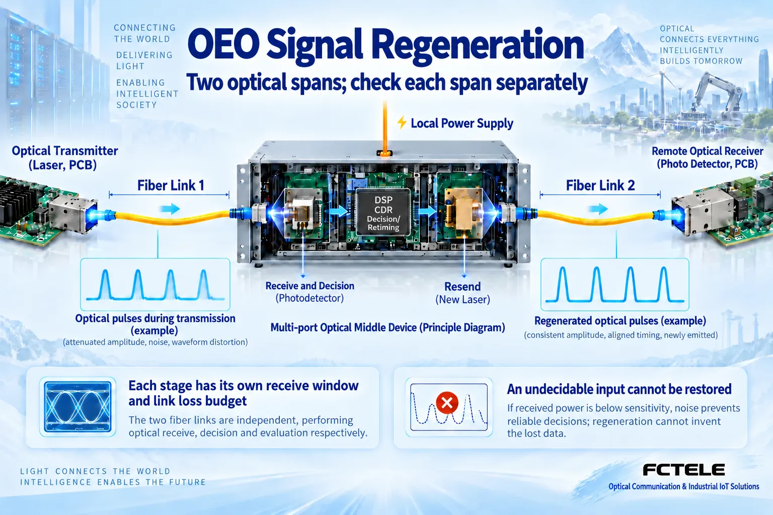
Optoelectronic regeneration first receives light, converts it to electricity and recovers usable data or line signals, then emits light through a new transmitter. Local power and transmit circuitry create the new output; the old light is not simply made brighter. Whether reamplification, reshaping and retiming occur, and how Ethernet frames are handled, depend on the architecture. A switching device retransmitting frames is not identical to a pure line regenerator.
5. Relaying can extend a route, but every segment must pass
If a route exceeds existing port conditions, consider an active relay or switching node at a suitable location to divide it into two segments. Verify pairing, fiber, losses, input window and speed separately for each. Inserting a single-optical-port converter into the middle of fiber cannot provide optical-in/optical-out forwarding. The design may need two compatible devices linked through copper ports or a device with suitable multiple optical ports. Confirm its forwarding architecture first.
A relay location needs power, space, cooling and maintenance access, and adds possible failure points and forwarding delay. Distance extension is not free of cost. If the first segment makes data unreadable, the second transmitter cannot know the original data. Incorrectly decided bits may be retransmitted, or damaged frames may be dropped. Make every segment receivable before evaluating end-to-end extension instead of adding an amplifier at the far end by trial and error.
6. What to check before extending the link
Check interface speed, single-/multimode fiber, wavelengths and power ranges first. Inspect and clean end faces, then measure receive power in both directions. With weak light, investigate connection losses, fibers and route. With overload, assess attenuation according to specifications. With normal power but faulty service, continue checking errors, negotiation, power and service configuration. Never look into an optical port or increase transmitter current or change unknown optical settings beyond component safety conditions.
FCTEL Gigabit-series documentation offers fiber-mode, power and interface options as an entry point for long-distance configurations. It does not establish that every version contains a dedicated optical amplifier or regeneration function. For a relay design, specify the number of optical-in/optical-out ports, each segment power budget, power supply and service-forwarding requirements to the supplier and obtain matching model documentation. Record segment power and round-trip data under actual load. Verify link indication, readable data and stable applications separately.
The final question is whether input conditions, decisions and timing support correct communication, rather than whether a waveform can be made taller. Ordinary point-to-point converters, dedicated regenerators and optical amplification systems have different roles. Similar names cannot replace their technical boundaries. Understanding these roles prevents using the wrong equipment for a fault better resolved by repairing fiber, matching interfaces or dividing the route.
References and illustration notes
Mechanism references:Analog Devices transimpedance amplifier documentation and clock and data recovery device documentation. These explain mechanisms; they are not evidence that FCTEL uses those chips. Product reference:FCTEL Gigabit-series details. Figures are generic illustrations, not measurements or model-specific cutaways.
Translated from the Chinese technical article. Source first published: 2024-11-20. Source last revised: 2026-10-13T16:50:29+08:00. Read the Chinese source
