


A converter losing communication is not necessarily frozen. Voltage dips, broken fiber, failed negotiation and congestion can all look unresponsive to software. Preserve evidence, distinguish power/link/service, then arrange restart or replacement. Recovery after reboot shows a state change; it does not prove the converter caused the fault.
1. Identify where data stops
The converter bridges copper electrical and optical signals. The copper PHY handles physical coding, reception and decisions; the optical transmitter emits corresponding data. The peer receiver converts light back for copper output. Reverse traffic follows another transmit/receive path. One lit endpoint cannot verify both directions.
Some units only convert media; others include switching and finite buffers. Managed models may add processors, logs and remote readings. An inaccessible management page, optical link loss, slow service and stopped forwarding are different symptoms. An unmanaged model may have no IP access at all, so no web page does not mean frozen hardware.
Record time, endpoint power/link LEDs, switch states, scope, self-recovery and preceding changes. Managed equipment may expose uptime, restart records and counters. Reset uptime suggests a restart; growing uptime with one down port suggests checking that link first. Interpret LEDs from the actual manual, not another brand colors.
2. Power and heat: a lit LED does not establish stable voltage
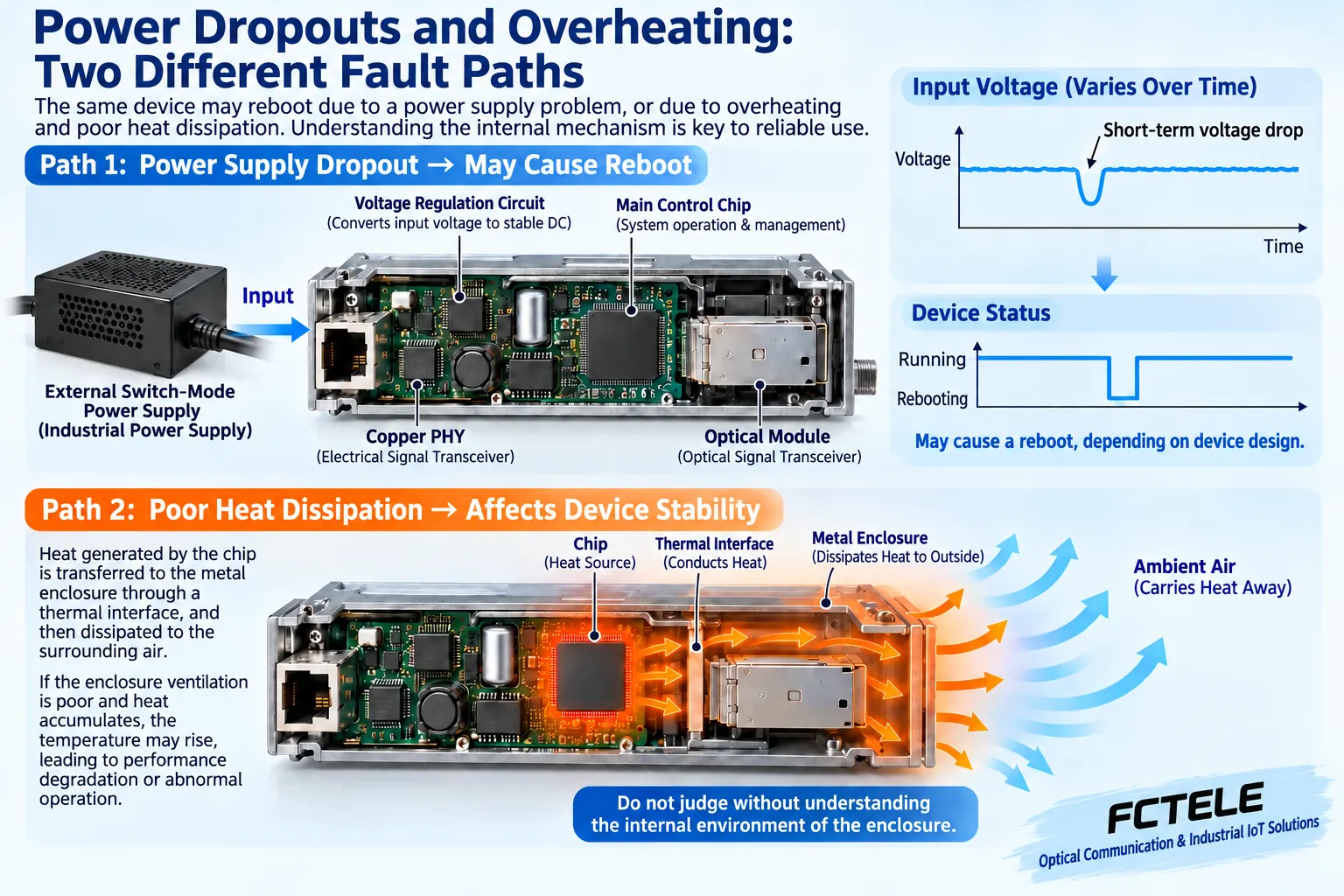
PWR mainly shows that a circuit has power, not that voltage remains valid throughout operation. Loose connectors, cable drop, inadequate adapters and transients can disturb internal rails, causing reset or link failure according to design. One multimeter reading may miss a short dip. Qualified personnel should capture transients with suitable instruments and procedures.
Check nameplate voltage, polarity, connectors and capacity. In an approved window, change only to a matching known-good supply and observe recurrence. Never open a live mains adapter or attach unknown supplies. Touch temperature cannot diagnose failure. Burning smells, damage or unusual heat require shutdown under site procedures and qualified inspection.
Heat travels from chips through conductive structures and enclosure to air. Dense cabinets, blocked paths, sunlight or high local temperature worsen conditions. Check actual installation conditions, not the room thermostat. Industrial-grade does not mean every temperature. Added ventilation must consider dust, condensation and protection. Do not remove housings indiscriminately or spray live equipment for cooling.
3. Check complete copper and optical round trips
With correct wiring/settings, establish a baseline using known-good copper and compatible short fiber, then reconnect the field route. Duplex TX reaches remote RX; BiDi needs complementary wavelengths. Check rate, fiber, connector and receive window. A fitting plug cannot establish optical compatibility.
Short links are not safer simply because light is stronger. Check overload for long-reach modules and design attenuation under the manual. Clean connectors and inspect bends/losses without looking into ports. Passing power is not passing traffic: check copper negotiation, errors and service. Only suitably equipped models expose power diagnostics.
If a switch shows flapping or increasing receive errors, locate cable, optics and port conditions first. Stable links with one failed application call for terminal, address, VLAN and service checks. Compare neighboring-port data rather than only converter LEDs. Change one supply, cable, optic or port at a time and retain wiring records.
4. Congestion is not equivalent to a freeze
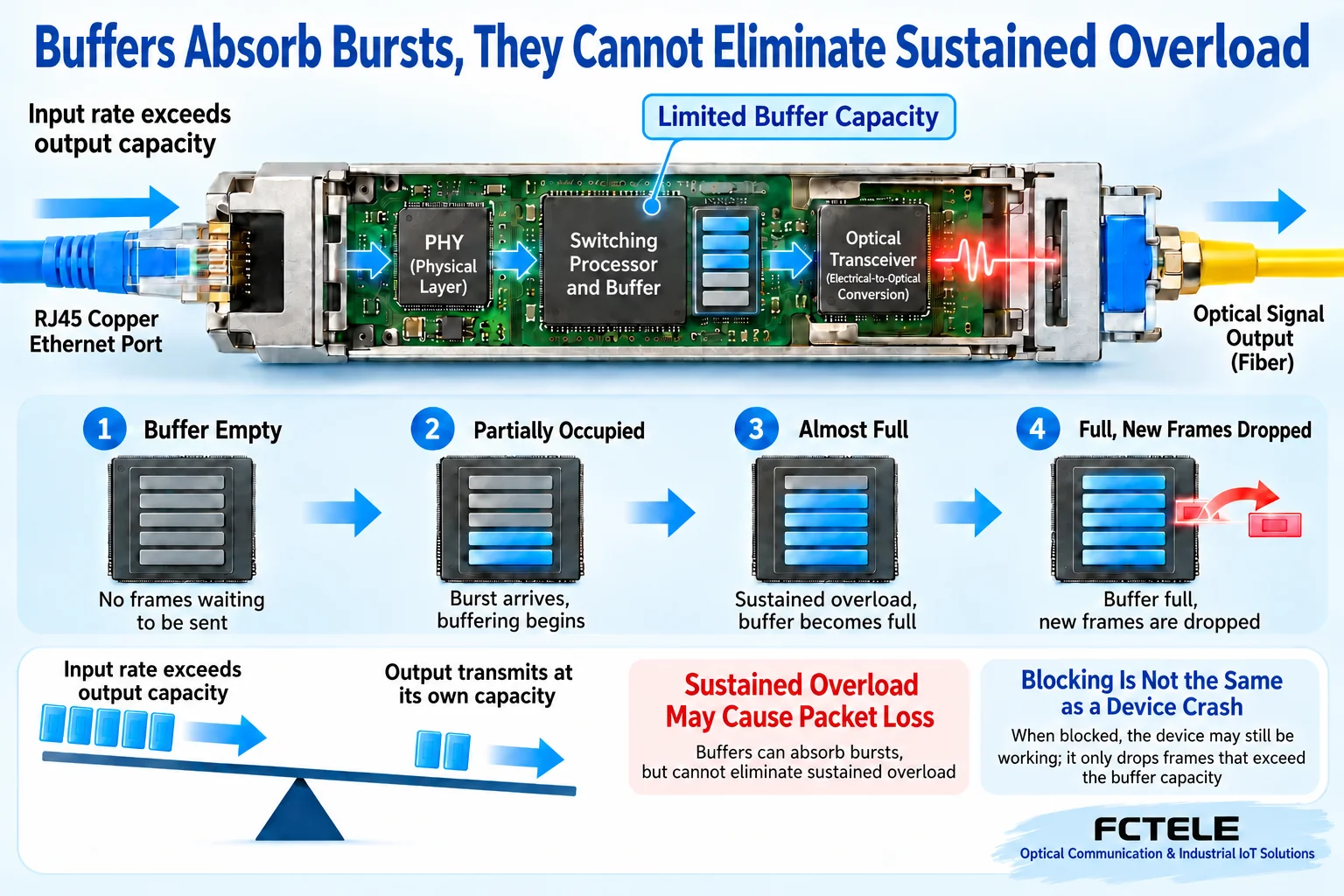
CRC detects certain Ethernet errors; it is not a freeze-diagnosis routine. A full buffer may queue, drop or apply flow control depending on design. Do not claim undetected bad frames remain forever and freeze every device, or that every converter checks complete frames at the same location.
If valid sustained input exceeds an output capacity, buffering delays congestion but cannot increase that capacity. Concurrent camera uploads, bursts and loops may raise load. Compare switch traffic and discard counters for bottlenecks. Do not deliberately create a production loop to demonstrate congestion; use authorized, isolated, rate-controlled tests.
An unknown destination MAC does not mean a frame stays in a buffer forever. Layer 2 unknown-unicast handling depends on switching and configuration. An old claim that an unlisted address is never transmitted is not universal. Check actual link flapping, error growth, recovery after reducing load and management response. If processing truly behaves abnormally, provide model/firmware evidence to the manufacturer.
5. Automatic reset helps recovery, not root-cause repair
Reset reinitializes state, may clear buffers/counters and rebuild links. It can recover certain abnormal states but interrupts service and erases clues. Capture evidence first, then reboot in an approved window. Repeated power cycling is not a long-term strategy. If the same load, temperature or power reproduces failure, continue investigating.
The FCTEL remotely managed single-port Gigabit external-power page lists freeze monitoring/self-reset, local/remote management, OAM frames and LFP. These may reduce some maintenance or expose endpoint status, subject to ordered version, compatible management peer and enablement. Self-reset does not remove every fault. LFP can show a related port down, not two independent failures. Do not apply these features to every FCTEL converter.
6. Use reproducible evidence for replacement and acceptance
For a hypothetical camera link failing every afternoon, compare timing with cabinet heat, supply disturbance and traffic peaks before blaming age. Test in isolation, then verify power, field fiber and load separately. A unit repeatedly failing on a safe short link with normal power/environment while a known-good replacement does not provides stronger hardware evidence. This is a diagnostic example, not a customer case.
Retest during the previously troublesome period and load: sustained bidirectional service, no unexplained flapping, expected error/discard behavior and no unplanned restart. Agree duration and limits per project, not a universal hour count. Retain topology, models/versions, power, substitutions, before/after symptoms and logs. Before firmware changes, confirm official model applicability, backups and recovery to avoid new downtime.
Translated from the Chinese technical article. Source first published: 2019-08-22. Source last revised: 2026-10-13T16:02:51+08:00. Read the Chinese source
