


A single-mode fiber media converter converts Ethernet electrical and optical signals on a suitable single-mode link. Single-mode describes light propagation, not a single physical core or a guaranteed distance. Match service interfaces first, then optical power, path loss and site operating conditions.
1. Identify the service being converted
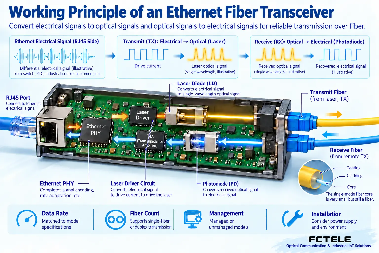
A common task connects a copper Ethernet device to the other end of fiber. The copper port processes matching Ethernet signals, and optical components transmit and receive. This changes the medium; it does not automatically become a video codec, serial gateway or carrier PON terminal.
Some units have fixed optics and others use pluggable modules. Neither the enclosure nor port count determines suitability. Verify copper speeds, optical standard and simultaneous multiport processing separately. Identical slots do not mean every module works.
Optics provide an entrance between two media for the supported service. RJ45 does not imply PoE, and an optical port does not imply every wavelength or distance. A product name cannot supply undocumented capabilities.
2. Specify classification dimensions separately
Single-/multimode concerns fiber and optical compatibility. Single-/dual-fiber mainly concerns the core count used for bidirectional communication. List these separately: single-mode equipment may use either single-fiber bidirectional or duplex-fiber transmission.
Speed, management, mounting and power are independent dimensions too. Desktop units suit certain indoor uses; rail-mounted units suit corresponding cabinets. Verify temperature, humidity and power variation against actual specifications. Industrial-grade does not mean suitable for every environment.
Managed units may add status and alarm functions; unmanaged units cannot be assumed to have them. A management interface cannot prove automatic recovery or recognition of every application fault. Define maintenance needs and choose documented functions.
3. Single-mode does not eliminate loss or delay
Under corresponding conditions, single-mode fiber mainly carries one spatial mode, reducing differences in arrival times between modes. Material and waveguide dispersion, fiber attenuation and connector loss still exist. Longer links require more conditions to be assessed.
Wavelength and receiver capability also affect reach. A distance label normally assumes a particular configuration and conditions. Connectors, splices and maintenance margin can change the installed result. Distance helps initial selection but cannot replace calculations and measurements.
Longer links add propagation time, and devices need processing time. Specify transmission method and supported service rather than promising zero latency. Validate industrial-control delays against complete system cycles and response requirements.
4. Do not confuse dB and dBm
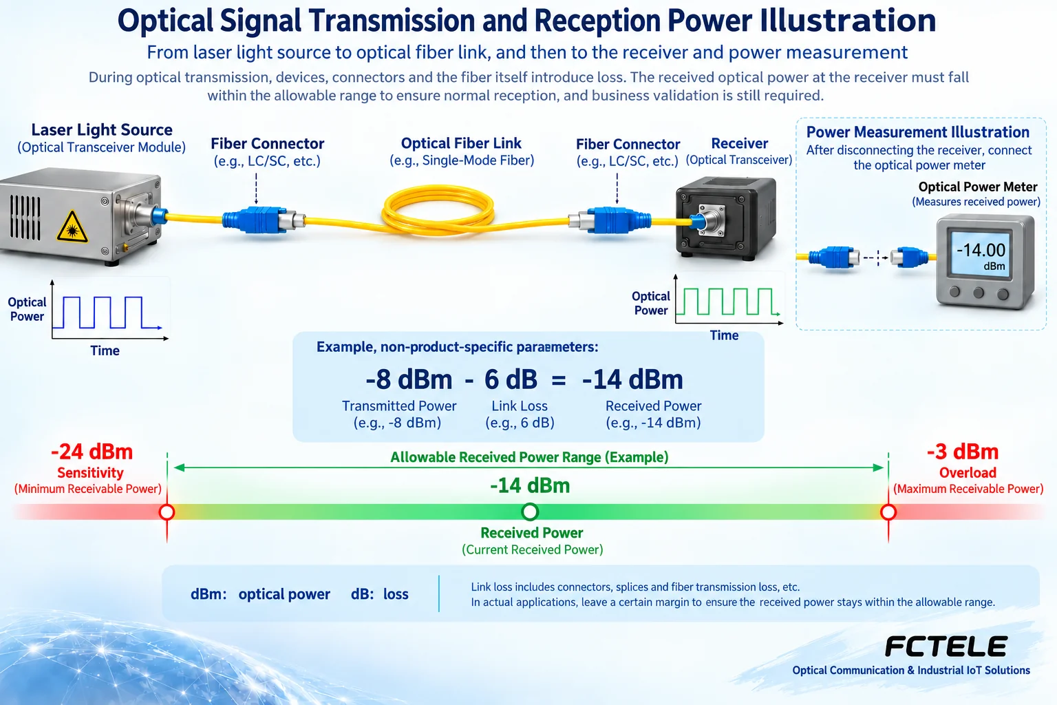
dBm expresses absolute power relative to a reference; dB commonly expresses loss or a ratio between powers. One states how much power there is; the other states how much it changes. Mixing units prevents correct comparison of transmitter output and line loss.
For illustration only, a transmitter at −8 dBm and total loss of 6 dB yield expected receive power of −14 dBm. These are not FCTEL product parameters or evidence that a line passed. Actual calculations need selected-component specifications and measured loss.
Receivers normally have both sensitivity and overload limits. Weak input may prevent stable recovery; excessive power may exceed conditions. More power is not always better, and long-reach optics are not automatically safe on very short jumpers. Verify any attenuation against component requirements.
5. Pair both directions correctly
Duplex fiber normally connects local TX to remote RX, with another core for the reverse direction. Single-fiber bidirectional links need complementary wavelengths rather than just opposite A/B labels. Endpoints also require compatible rates, modes and optical interface behavior.
Budget each direction separately. Endpoint transmit and receive capabilities may differ. Seeing light in one direction does not prove the reverse passes. Preserve wavelengths, component models, core identifiers and directional measurements for future checks.
FCTEL managed Gigabit converter information provides a model-specific selection source. For status monitoring or centralized maintenance, verify features and optics in that category rather than assigning identical speed, power redundancy and temperature ranges to every converter.
6. Complete a reliable site selection
If two buildings already have single-mode fiber, establish endpoint Ethernet rates, available cores and patch-panel locations. Select compatible endpoints, total fiber/connector/splice losses, verify the receive window and margin, then check power and mounting.
Before deployment, verify endpoints on a suitable short link, then measure and test traffic on the actual route. Prevent excessive short-link input too. Test normal load, sustained operation and recovery instead of relying on LEDs or one ping.
Hand over service type, interface rates, fiber mode, core count, wavelength pairing, power ranges and measurements. Future repairs can then choose compatible replacements rather than guessing from a single-mode 20-kilometer label.
References:Cisco Gigabit optical module specifications;FCTEL managed converters. Figures explain generic mechanisms, not measurements or model-specific wiring.
Translated from the Chinese technical article. Source first published: 2019-10-29. Source last revised: 2026-10-13T16:02:51+08:00. Read the Chinese source
