


A multimode fiber media converter has no universal price independent of configuration. Identify existing fiber, endpoint speeds, optical conditions and installation environment before comparing quotations that include power, modules and accessories. Distinguish two limits: loss may make the signal too weak, while pulse spreading can make data unreadable even with normal power. Neither power measurement nor an illuminated LED completes purchase acceptance.
1. What does a multimode converter connect?
An Ethernet media converter provides the required signal conversion between copper and fiber interfaces. In transmission, copper-side circuitry processes terminal signals and the optical transmitter turns electrical information into light. In reception, a photodetector converts light to electricity and subsequent circuits recover supported output signals. It does not directly put an entire image or file into fiber, nor automatically understand every video, serial or telephone protocol.
Multimode describes the propagation modes allowed by the fiber, not multiple service channels. Modes are different propagation states within one core, not separate fibers. Single- versus dual-fiber is another dimension: the physical core count used by a link. A typical duplex link uses separate directions, with local TX connected to remote RX. Multimode units or modules still need compatible hosts and peers.
2. Why adequate power may still produce communication errors
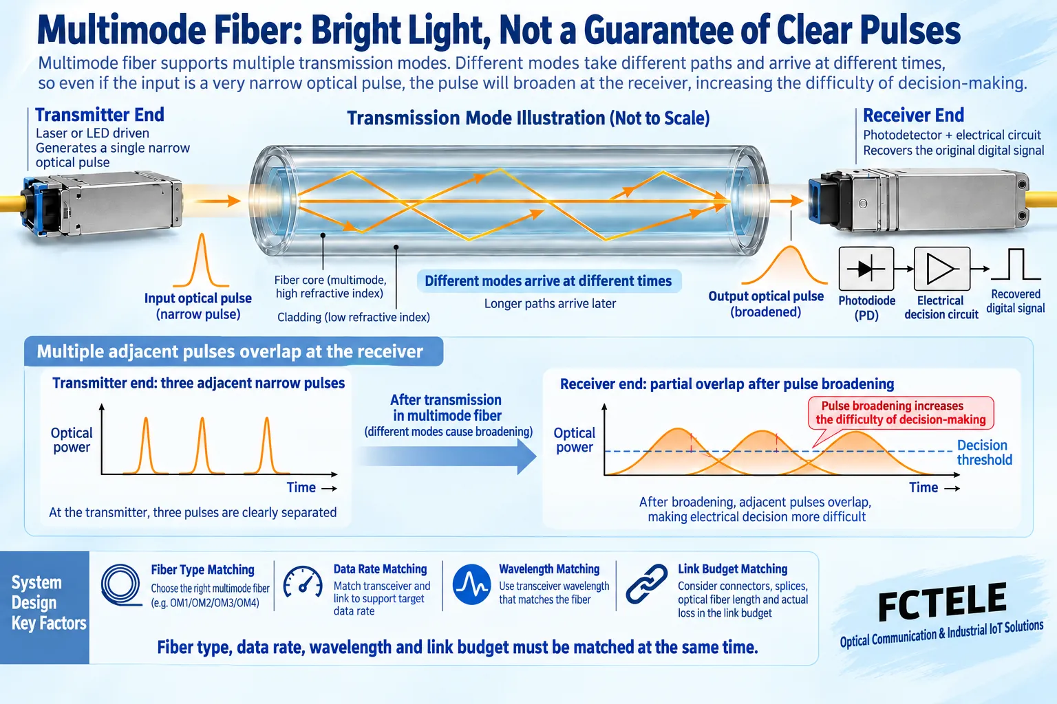
Different modes in multimode fiber can reach the receiver at different times. A narrow input pulse may broaden on arrival, making adjacent pulses harder to separate. This is modal dispersion. Here dispersion is not simply dimmer light: the information shape changes in time. Illustrated paths simplify the explanation rather than accurately plotting actual modal fields.
Higher rates allocate less time to each bit and change tolerance to spreading and timing. An older working Fast Ethernet link does not prove suitability after an upgrade to Gigabit or faster equipment. Received power tells us how much light arrives, not whether pulses remain distinguishable. Evaluate fiber grade, interface standard, wavelength, length and rate together rather than comparing only the word multimode.
3. Check installed fiber before choosing the cheapest box
Use cable labels, as-built documentation and test records to establish fiber type and grade, such as its documented OM category. Then check length, connectors and splices. Jacket color is a clue rather than complete identification. Qualified personnel should investigate undocumented older lines. Verify that jumpers and permanent fiber match; replacing only short endpoint jumpers cannot correct an unsuitable intermediate cable.
Official module documentation normally lists reach by interface and fiber type, not one distance for every multimode device. For example, Cisco 10GBASE-SR data lists different distances for different multimode grades. That illustrates a selection method; its parameters are not FCTEL complete-unit specifications or guarantees for an arbitrary Gigabit model. Order against target-model documentation and the actual link.
4. Include hosts, power and both optical endpoints in the quote
Fixed-optics devices normally include optical components, while pluggable designs require confirmation that supported modules are included. Mechanically matching connectors do not establish equal wavelengths or rates. Adaptive copper speed does not mean arbitrary optical speeds. Define both traffic directions and determine whether the peer already has compatible optics before calculating quantities. A quote for one device is not necessarily the price of a complete link.
Specify power input, included adapters, brackets, jumpers, spares and installation costs. Central rack power and separate adapters have different costs. Central installation also requires cabinet space and consideration of shared-fault scope. Internal/external power alone does not define carrier or consumer grade. A metal enclosure cannot prove temperature, protection or management capabilities. Align delivery conditions before comparing prices.
The FCTEL B-series single-port Gigabit page includes multimode duplex optical options for checking existing multimode Ethernet links. Confirm power form, buffers and frame-length support for the ordered version. Options listed on one page are not necessarily all present simultaneously. For old-fiber upgrades, provide fiber documentation and request confirmation of modules, interfaces and reach rather than asking only for a multimode price.
5. Optical power acceptance checks the receive window
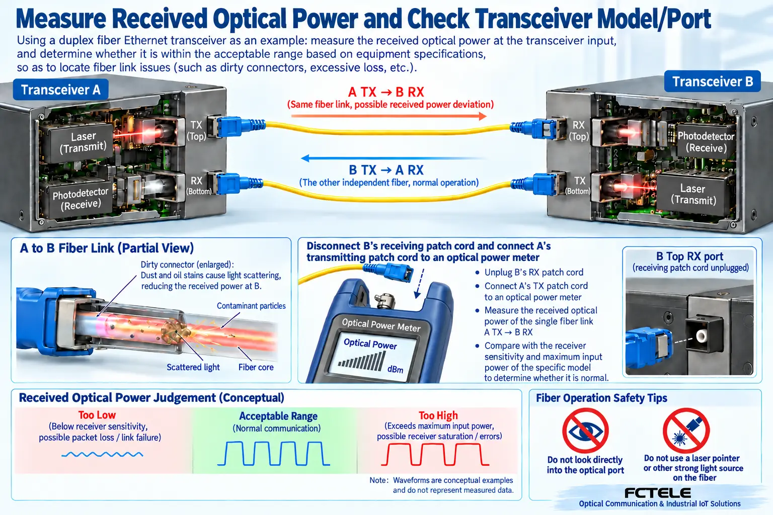
Path loss includes fiber, connectors and splices. Check both directions separately. A receiver has sensitivity conditions and a maximum input; either weak or excessive light can cause problems. Use a power meter suitable for the wavelength, connect according to procedure, record receive power and compare it with documentation for that version. An arbitrary negative reading is not automatically normal.
Inspect and clean connectors using suitable procedures before measuring. Never look into unknown optical ports, touch end faces or introduce contamination. Check input conditions even on a short baseline link; high-power long-reach ports cannot be directly connected indiscriminately. If receive power is suitable but errors remain, investigate fiber type, interface, spreading, terminals and traffic rather than repeatedly increasing transmitter power.
6. Finish acceptance with actual services, not just ping
First use suitable short fiber and known-good terminals in an isolated test, then introduce the installed cable to separate device, jumper, line and terminal issues. Cover target rate, actual frame lengths and bidirectional load, recording errors, loss, delay changes and operating conditions. Ping provides partial reachability evidence, but a few small replies cannot prove peak throughput or complete application acceptance.
Accept copper sections against the relevant interface and cabling requirements. A 120-meter ordinary Ethernet cable is not a universal requirement every model must support. Use a maintenance window for production tests and record power/link-failure recovery. Do not disrupt active systems merely to test maximum load. Interpret LEDs using the actual manual rather than another brand panel.
Retain host/module models, endpoint parameters, fiber identifiers, power, test conditions and results. Define support scope and quotation validity. Enclosure wear is an inspection clue, not proof of internal component age or quality. The aim is a suitable, testable, maintainable link rather than a permanent configuration-free price number.
Further mechanism reference:Cisco: single-mode and multimode fiber explains how modal dispersion broadens pulses in time and can cause neighboring pulses to overlap. Illustrated propagation paths are simplified, not measurements of a particular fiber.
Translated from the Chinese technical article. Source first published: 2020-04-02. Source last revised: 2026-10-13T16:50:29+08:00. Read the Chinese source
