


FIBER RETURN LOSS, AT A GLANCE
Why can a higher loss reading be better?
Return loss describes light coming back, not forward attenuation. With the common positive convention, a higher reading means weaker return relative to incident light. Reflectance often uses the opposite sign. Compare only matching definitions, reference planes and measurement scope, then apply the requirements of the actual optical system.
Follow both directions
Insertion loss concerns forward transmission. Return loss concerns light returning toward the source.
Check the sign
Under matching definitions, more negative reflectance and higher positive return loss indicate less return.
Define the scope
A connection event and the combined return of a measured span are different objects.
Identify the parameter
Record whether the report gives insertion loss, event reflectance or whole-span ORL.
Match the conditions
Compare wavelength, direction, reference planes and far-end treatment.
Verify the service
Retain optical results with power, error counters and application evidence.
Selection and verification checklist — expand
| Check | What to confirm | How to verify |
|---|---|---|
| Parameter | Name, sign and scope | Read the instrument definition. |
| Connection | Compatible interface and end-face type | Check component documentation. |
| Reference | Direction, wavelength and reference planes | Retain the setup record. |
| Far end | Treatment and included span | Follow the instrument method. |
| Evidence | Optical and service results | Keep traces, settings and error records. |
Conceptual diagrams, not measurements, product internals or wiring instructions.
A fiber test report may ask for low loss in one column and high return loss in another. Reflectance may even be negative. Has the instrument reversed the result? Usually not. The measurements concern different directions of light and use different conventions. Establish where light enters and returns before treating passing insertion loss as proof that every optical requirement is met. This guide explains principles rather than universal acceptance limits.
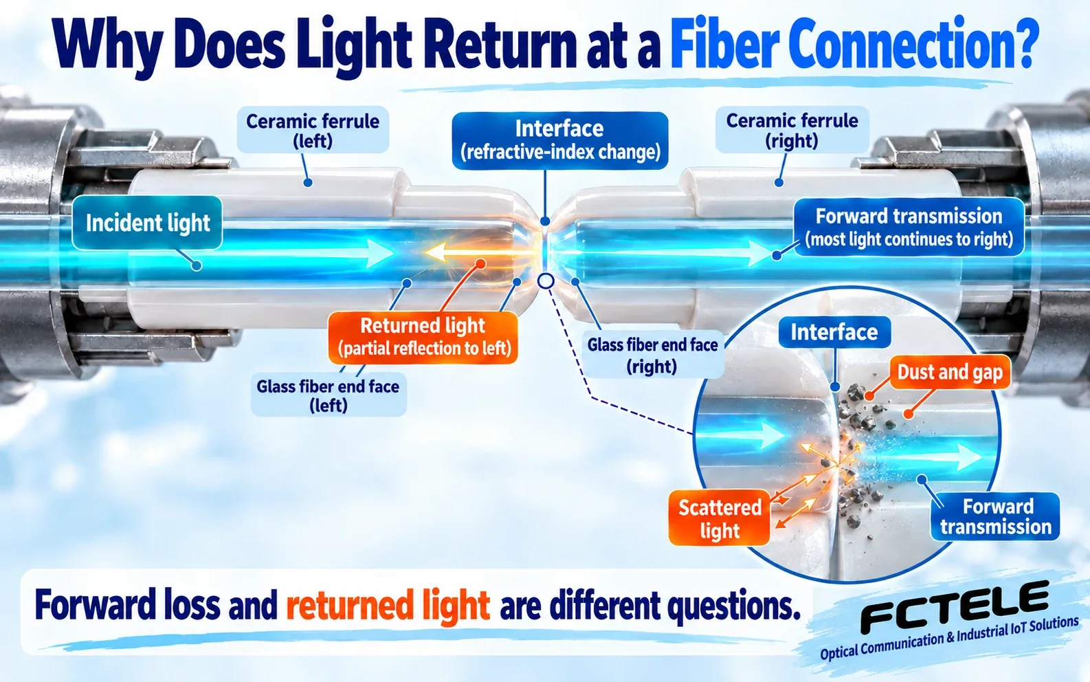
Forward loss and returned light answer different questions
A transmitter launches light into fiber, and the receiver needs a usable signal. A connection can reduce forward transmission while returning some light toward the source. Insertion loss concerns the reduction in forward transmission introduced by a connection or link. Reflection-related measurements concern light traveling back toward the launch side. Both can relate to connection quality, but neither replaces the other.
Think of people entering and leaving a corridor: fewer people reaching the exit does not identify how many turned back. This analogy distinguishes direction only. Optical reflection depends on interfaces and waveguide conditions; light does not choose a route. First identify the measurement, direction and unit rather than comparing the numbers.
Why a connection returns some light
At an interface where material properties change, part of the optical energy can be reflected. This is commonly called Fresnel reflection. Fiber cores within mating ferrules need alignment and appropriate end-face contact. An air gap, contamination or damage can change interface conditions. The illustration exaggerates interfaces, gaps and particles; it is not a dimensional drawing.
Reflection does not mean all light is blocked. One connection can transmit light forward, return some and introduce other losses. A reflection peak does not prove dust is present. Connection geometry, an unconnected end, mechanical joints or other events can produce a return. Position, connection records and suitable inspection methods are needed to identify the cause.
Why higher return loss usually means less return
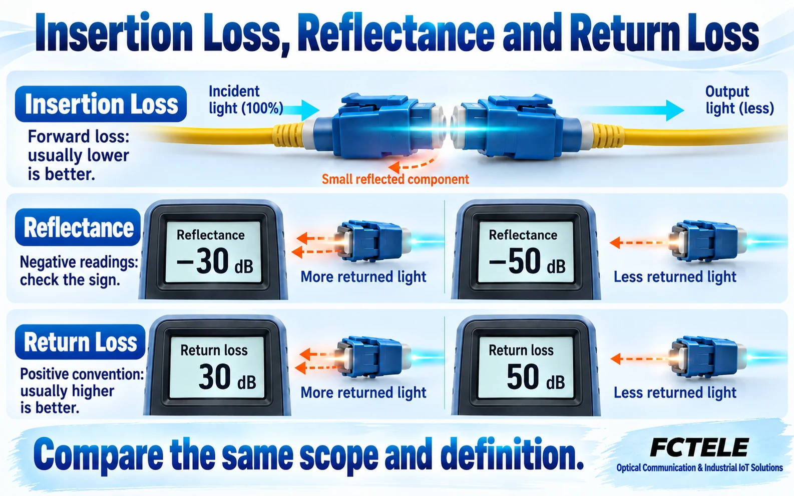
Under the common positive-number convention, return loss expresses the separation between incident and returned optical power. Weaker returned light means greater separation and a higher return-loss reading. It does not mean the signal traveling toward the receiver has lost more power. Insertion loss describes the forward path, so its usual lower-is-better rule cannot simply be transferred to return loss.
Reflectance is often negative. For the same ratio, reference plane and measurement scope, minus fifty reflectance and plus fifty return loss can express opposite conventions for the same comparison. Minus fifty indicates less returned light than minus thirty. Do not look only at the digits. Names and signs may vary between documents; establish the instrument definition before comparing results.
Suppose two readings at the same reference plane change from thirty to fifty. If the parameter explicitly uses positive return loss, the return has become weaker relative to incident light. Treating the same change in insertion loss as an improvement would be wrong. These numbers teach interpretation; they are not network targets or a reason to change acceptance thresholds.
A connection event is not the entire link
ORL stands for optical return loss. A report may use ORL for the complete measured span, combining reflections at several connections with backscatter distributed along the fiber. Distributed backscatter and concentrated reflection at one connection have different trace signatures. Length, direction and included span can affect a combined result.
Event reflectance concerns one location. Whole-link ORL concerns return within the measurement scope. Ranking a connector reflectance against the ORL of an entire cable makes little engineering sense without matching definitions. Record the parameter, start and end reference planes and direction so another reviewer knows what was tested.
A short patch-cord test and a long cable with several patching locations are different objects even if both reports use the word return. Attach a sketch showing the test port, reference connection and span boundaries. Record direction when testing from the other end instead of treating a difference between conditions as an instrument fault.
End-face finish matters, but color is not enough
Physical-contact finishes use appropriate geometry to help fiber end faces meet. An angled finish also makes reflected light less likely to couple back into the backward-propagating core mode. This changes return coupling; it does not increase bandwidth or make contamination and damage irrelevant.
Do not force different end-face types together because one connector appears more advanced. Match interfaces, patch cords and adapters to equipment requirements. Housing color is a clue, not a substitute for markings and documentation. Record the original connection and service state before changing parts. One connector adjustment does not validate an entire system design.
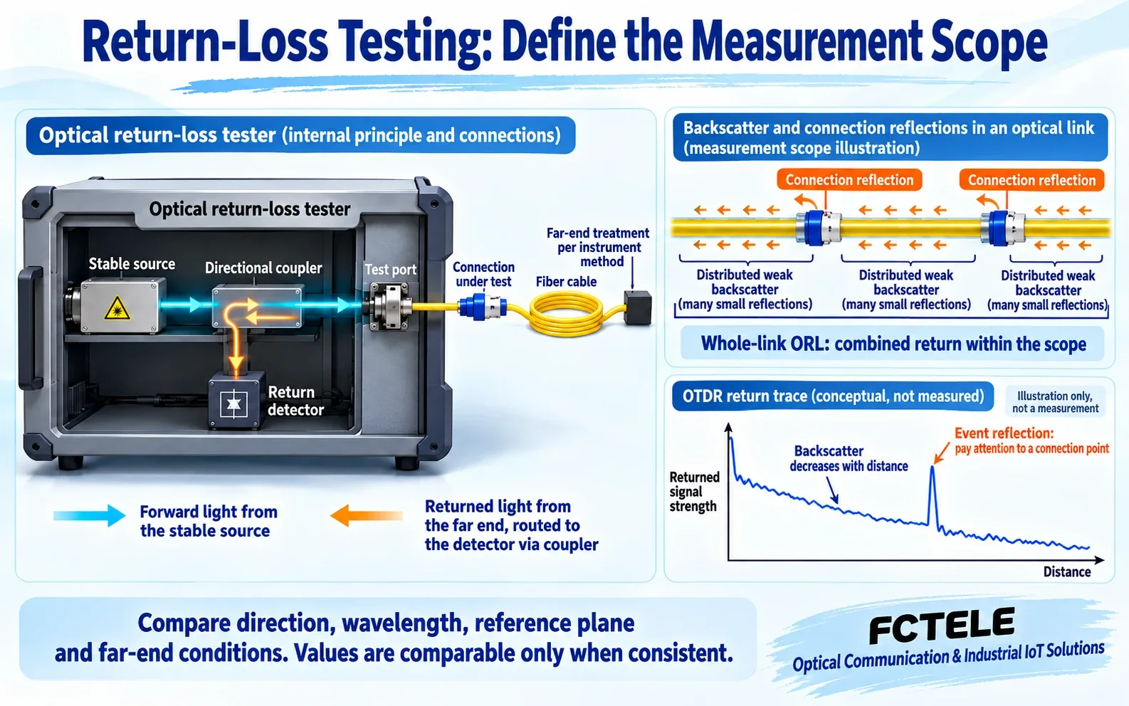
A tester must detect the intended returned light
One measurement approach uses a directional coupler to send source light toward the item under test and route returned light to a detector. Actual instruments account for reference power, internal return, dynamic range and reference planes. An ordinary power meter at the far end does not by itself measure return loss. Whether far-end reflection is included also affects the result.
An optical time-domain reflectometer, or OTDR, uses return versus distance to help locate events. Some instruments also analyze reflectance or ORL. If a reflection saturates the receiver and its peak becomes flat-topped, the reading cannot be interpreted as an ordinary valid event. Many display digits do not establish equal measurement accuracy. Retain raw traces and settings according to instrument instructions.
Match conditions before deciding whether a link passes
Match wavelength, direction, reference planes, far-end treatment, span and instrument state before comparing reports. Follow applicable inspection, cleaning and connection procedures. Do not tightly coil a field patch cord or introduce undocumented attenuation merely to improve a return reading: that changes the object being tested and may damage it.
FCTEL managed industrial-switch documentation identifies real copper and SFP configurations. Reflection tolerance still requires the selected optical module and system documentation. An SFP slot does not repair a bad end face or eliminate reflection. These illustrations do not show the internals of a particular FCTEL model.
Combine optical results with received power, error counters, service stability, test time and changes before and after an operation. Insertion loss, return and application quality observe different aspects. Passing one does not establish that the others pass. Establish definitions, align conditions and judge against actual system requirements.
Confirm the file belongs to this link, check the parameter and sign, inspect conditions, then read the acceptance decision. Complete missing records before replacing equipment. Repeatable records let future maintainers distinguish changes in the fiber, connection and test arrangement.
Sources: FOA: reflectance and return-loss measurement; Santec/OptoTest: single-mode connections; Fluke Networks: return-loss conventions; EXFO: fiber characterization; FCTEL industrial-switch documentation (Chinese). Teaching illustrations and hypothetical examples do not replace specifications, standards or acceptance procedures.
Common practical questions
Does higher return loss mean greater forward loss?
No. Common positive return loss describes how weak the return is relative to incident light. A higher value usually means less return. Insertion loss concerns the forward path and uses a different comparison.
Can event reflectance be directly ranked against whole-link ORL?
Not without matching definitions and scope. Check the instrument convention, sign, direction, reference planes and measured span before assessing the result against actual system requirements.
Does normal received power rule out reflection concerns?
No. Received power, returned light and service errors observe different aspects. Check the optical parameters and service evidence required for the actual system instead of inventing a universal threshold.
Scope and further reading
General principles and hypothetical examples, not product measurements or a universal acceptance procedure.
Optical dispersion and signal shape · OTDR events and dead zones (Chinese)
