


First record the symptoms and keep the original configuration
An audio optical transceiver may have power and a lit optical light but no sound at the far end; this is not necessarily a fiber cable problem. Input type, channel mapping, receiver output, amplifier mute, and source settings can all affect final playback. When troubleshooting, first record which direction, which channels, and at what time the abnormality occurred, and whether cables, power supplies, or devices were recently changed or adjusted. Do not start by replacing the entire system at once.
No sound, intermittent sound, continuous hum, and distortion are different phenomena. They can help choose the order of checks, but they cannot by themselves give a definite root cause based only on listening. First lower the playback volume, and within the allowed range use a known source and compatible downstream equipment to establish a baseline; change only one condition at a time, and keep a record of whether the phenomenon follows a particular device or channel.
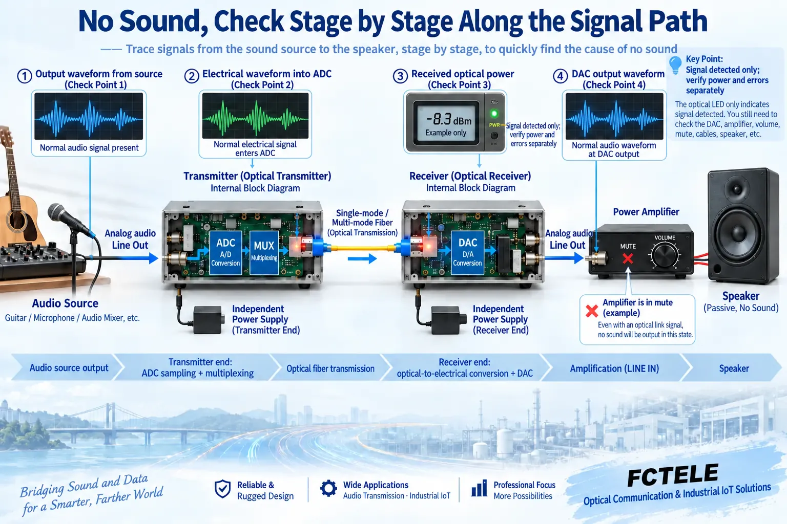
For no sound, first check segment by segment from source output to downstream input
Confirm that the source device is truly outputting from the planned OUT and is not muted or switched to another connector; then check the signal type and allowed level of the transmitter IN. The receiver OUT must connect to the downstream IN; do not connect two outputs to each other. Left and right channels, numbering, and direction should also be checked, especially for bidirectional products: sound in the forward direction does not prove that the return port is connected correctly.
A microphone connected to an ordinary line input may have insufficient level, while an amplifier power output connected to a line input may overload or even damage it. Enable phantom power only according to the instructions for applicable devices. Ordinary telephone lines carry power and ringing conditions, so audio ports must not be used to test lines; digital AES input and analog XLR have the same shape but also require completely different receiving processing.
Optical path checks must look at both compatibility and the receiving window
The transmitter and receiver device models, fiber type, connectors, wavelength combination, and line coding must be compatible. Dual-fiber usually means local TX to remote RX, with another fiber for the reverse direction; for single-fiber products, check according to the manufacturer’s combination. The fact that a connector can be inserted does not prove compatibility, and single-mode, multimode, or other optical versions cannot be interchanged based on kilometer labels.
Use a suitable optical power meter to check the receiving conditions; the wavelength setting and measurement direction must be correct. Too little light, contaminated connectors, or excessive bending may affect decisions, and too much light may also exceed the receiver’s allowed range. Light status is only partial evidence and is not directly equivalent to acceptable bit errors or normal sound. Use appropriate tools to inspect end faces; do not look directly into optical ports, and do not touch end faces with your hands to clean them.
A short link can help distinguish line and equipment conditions
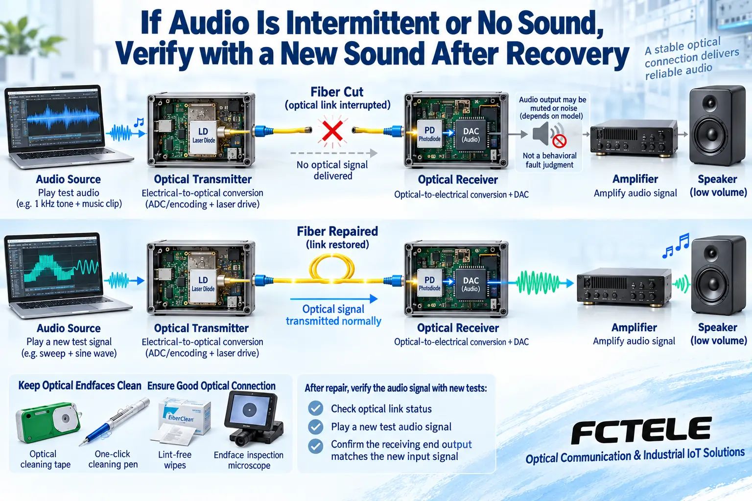
Keep the same pair of devices, source, and downstream settings, and replace the installed fiber cable with a known short patch cord that meets the receiver overload conditions. If the short link is normal but the installed fiber cable is abnormal, first check the fiber cable and connection loss; if both are abnormal, continue checking power, access, and device configuration. Multiple replacements without records can easily make a fault temporarily disappear without knowing the cause.
For intermittent abnormalities, also compare power at both ends, connector movement, temperature, and the status of shared services. All channels changing at the same time versus a single channel changing suggests different shared conditions. Enclosure checks and low-voltage connection checks must follow the manual; for internal power, hazardous power circuits, damaged components, or protective grounding, have qualified personnel handle it, and do not use power-on testing with the enclosure opened as an ordinary troubleshooting step.
For distortion and noise, first check the signal before it enters the fiber
When an analog input exceeds the allowed range, the peaks of the waveform are flattened, which is called clipping. The ADC samples this distorted voltage, and even if the digital link is normal, it will send the distortion to the far end; the receiving DAC will not automatically restore the original waveform. If the input is too small and the downstream equipment amplifies it greatly, front-end noise will also become louder. Record gain, source level, and load, then adjust the matching relationship.
Continuous hum may be related to local analog cables, reference, and power; the fact that the middle fiber segment has no ordinary copper conduction does not mean the entire system is free of interference. Balanced inputs can suppress only some common interference under suitable conditions, and this cannot be handled by arbitrarily disconnecting protective grounding. For specific noise localization, refer to the separate noise topic, and do not explain all abnormalities as optical power changes.
Multi-service models must verify each interface separately
Some products can be configured with serial, video, Ethernet, or discrete contacts; audio recovery does not prove that these services are also normal. For serial ports, also check port definitions, rate, and actual communication; for discrete contacts, check the interface form and load, and do not guess the state based only on terminal voltage. Ordinary audio fault procedures also cannot replace video format matching or network configuration checks.
Feichang FCA-A4-L introduces RCA audio and corresponding service options. Troubleshooting should correspond to the ports, levels, and channels of the ordered version, rather than assuming that all ports exist based on a series introduction. The loss-of-light identification, alarm, or recovery capabilities in the documentation require checking the actual configuration and test results; do not use current values from other models in historical articles as the basis for on-site wiring.
After repair, confirm that new sound arrives and record the recovery process
After restoring the optical connection or power, observe the receiving status, muting, and service recovery. The behavior during loss of light and whether it automatically recovers vary by model, and seamless switching is not universally promised. Use a known sound or test signal from a new input to confirm that the corresponding receiver output gets new content, and check channel direction and downstream settings one by one; do not just look at whether the light comes back on.
If latency, distortion, or continuous operation needs to be tested, use clear measurement points and suitable instruments, and keep the same conditions before and after repair. For bidirectional services and multi-remote broadcasts, test each direction and location separately. Perform firmware upgrades only when the manufacturer confirms it is necessary, the version is compatible, and a maintenance window is arranged; do not treat unsupported upgrades as the first choice for any fault.
Maintenance should leave reusable evidence
Keep endpoint and interface documentation, channel diagrams, gain, power, optical power, and fault occurrence times. Regularly check mounting, heat dissipation, fiber cable protection, and end face condition, and arrange maintenance according to the environment and usage intensity; do not use frequent plugging and unplugging instead of diagnosis, and do not casually use cleaning fluids on unknown devices. Spare parts should be compatible with the existing optical and service configuration; different models require re-checking.
The handover report should state the symptoms, the single conditions changed, the repair measures, and the retest results. During continuous operation, also observe whether the abnormality recurs and keep alarm and status records. On-site checks that can be completed safely are limited to permitted external connections and configuration; anything beyond that should be handled by the manufacturer or professionals, to avoid expanding equipment damage just to investigate one sound fault.
Documentation note: The principle diagrams have been checked against technical content and are used to explain general mechanisms; they are not physical product photos or measured records. Specific interfaces, modes, and capabilities are subject to the selected model, version, and on-site verification.
Verification materials:TI: Common-mode rejection of balanced audio inputs
Feichang FCA-A4-L product documentation
TI PCM186x audio ADC documentation
ITU-T G.652 single-mode fiber specification
Related technical topics:How to look at audio optical transceiver sampling and sound quality: sample rate, bit depth, noise, and distortionHow far can an audio optical transceiver transmit: optical power budget, receiving window, and stability acceptanceHow to choose an audio optical transceiver: analog and digital interfaces, channel direction, and acceptance indicatorsHow to wire an audio optical transceiver: line level, two bidirectional channels, and broadcast distributionWhere can an audio optical transceiver be used? Digital transmission principles, applications, and access boundariesHow to connect professional audio to an audio optical transceiver? Level, channels, and stage return acceptanceWhy does an audio optical transceiver have noise: input level, common-mode interference, and segment-by-segment localizationWhat is the difference between an audio optical transceiver and a telephone optical transceiver: sound waveforms and call status must be separated
Translated from the Chinese technical article. Source first published: 2024-04-23. Source last revised: 2026-10-13T11:44:53+08:00. Read the Chinese source
