


Why one extra cable can slow down the whole network
When an uncontrolled loop path appears in a Layer 2 network, broadcast, unknown unicast, and similar frames may be forwarded repeatedly, consuming link and device resources. On site, mistakenly connecting two access ports to the same downstream device, or casually plugging a spare cable back into the network, can cause problems. Loop detection is a mechanism that helps discover this kind of connection, but you cannot judge that a service loop has formed just by seeing cables arranged in a circle.
A physical spare connection is different from logical repeated forwarding. A correctly configured spanning tree or ring protection can keep some service paths in controlled blocking, leaving a loop-free forwarding relationship. Conversely, two cables that look like ordinary uplinks may connect to the same broadcast domain somewhere else. Troubleshooting needs to combine the actual topology, VLANs, port states, and counters, and not directly judge all ring-shaped cabling as wrong.
What clues does a probe frame returning to the local device provide?
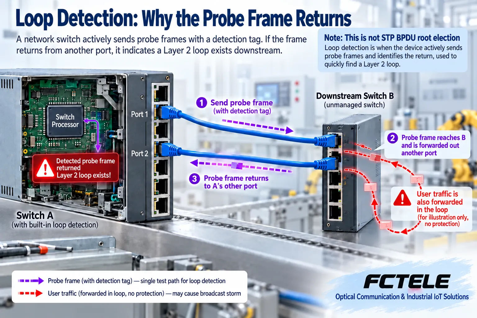
One common loop detection implementation sends probe frames with identification information from participating ports and observes whether they return to the local device along the network. When a corresponding loop path exists downstream, the device can identify the returned probe information and then record or handle it according to supported policies. The specific frame format, check scope, and port judgment are determined by the implementation; not all devices called loop detection use exactly the same method.
Using the teaching example where two ports of switch A are mistakenly connected to downstream switch B, a probe frame may leave from one port of A and return to another port of A through B. This return indicates that the corresponding path needs to be checked, but it does not directly point out which cable was just connected incorrectly. The device also needs to identify the sending source, ingress, and related states according to rules. Logs and topology should be saved together; you cannot just see a text message saying “loop detected” and pull cables at random.
Alarm and port shutdown are two choices
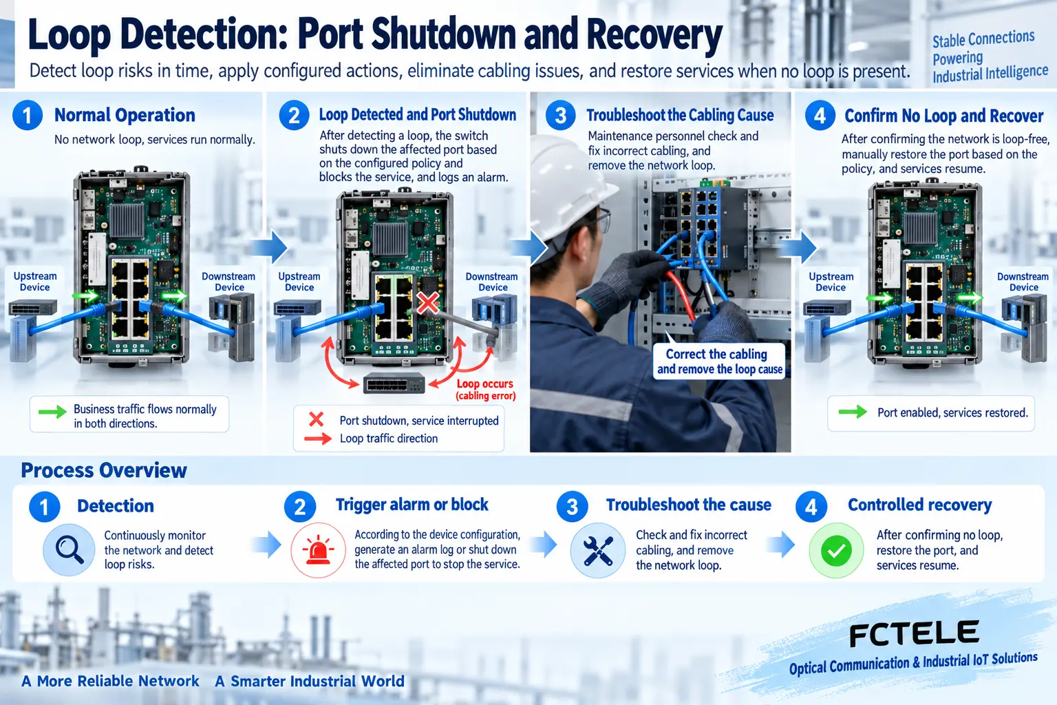
Some configurations only record logs or send notifications, while others also shut down related ports or limit forwarding according to supported methods. An alarm lets the administrator know an abnormality exists, while shutdown actively changes the communication path; the service impact of the two is different. A port entering a protection state does not mean the interface chip is damaged, and you cannot immediately replace the switch just because you see a light go out.
Which port is shut down, whether other VLANs are affected, and whether the management path can be preserved all need to correspond to the local policy. When an uplink carries multiple control or video streams, one block may take multiple terminals offline. Before deployment, you should clearly write down what type of wiring error is to be discovered, which services may be interrupted, and how to roll back, rather than setting all ports to the same action and expecting the device to automatically judge service priority.
Loop detection does not replace spanning tree and ring protection
Spanning tree establishes a loop-free service path through control messages and port roles, while ring protection coordinates normal and fault states according to the corresponding mechanism. Loop detection probes whether a specific return phenomenon currently appears; their responsibilities are not the same. It cannot automatically provide the full spare path design, nor can it guarantee that all important services are still reachable after one port is shut down.
When different mechanisms coexist, the reachable range of probe frames, controlled blocking, and recovery behavior affect each other. You should configure participating ports and scope according to the specific model documentation, and verify the combination in an isolated environment, rather than directly following another brand’s rules to decide who has priority. Broadcast storm suppression only limits a certain type of traffic; it cannot prove that the loop has been removed. Services after rate limiting may still be affected by repeated forwarding.
Why self-recovery cannot be treated as fixed
Automatically re-enabling a port is only the device attempting recovery under supported conditions; if the wiring error still exists, detection and shutdown may be triggered again. Repeated up and down events can affect terminal sessions and may also flood logs with a large number of repeated events. The detection and self-recovery periods in the original text are examples for a specific interface and cannot be used as uniform seconds for all industrial switches.
Before recovery, you should locate the return path, check newly added connections, downstream devices, and VLAN relationships, eliminate the actual cause, and then recover under control according to the plan. Necessary manual recovery, waiting conditions, and whether configuration needs to be saved should be checked in the corresponding version manual. Without evidence, do not repeatedly force ports open, and even less should you prove that a cable “can connect” by disabling loop prevention functions across the entire network.
Check FCTEL devices separately according to public functions and documentation
The FCTEL product 2241 managed four-fiber eight-copper switch page lists capability directions such as STP, RSTP, MSTP, ERPS, and storm suppression. This proves that the corresponding path control and traffic protection can be further evaluated, but these names alone cannot be used to assume that a certain vendor-proprietary probe frame format, port self-recovery algorithm, or default period is already present.
When a project needs dedicated loop detection, you should confirm with the supplier whether the delivered model and firmware support it, where to enable it, how to view logs, and how to remove protection. Whether both optical and electrical ports can participate and which VLANs are affected should also be clarified. Third-party Loop Detection Guard material is only used to explain one generic implementation; it does not provide FCTEL universal configuration commands, nor does it replace local function evidence.
Verify actions in an isolated environment first
Prepare representative devices and recoverable configurations, first establish normal loop-free communication, then simulate the target wiring error in an isolated test network according to the approved plan, and observe detection, alarms, port handling, and real services. Do not put a test that creates a broadcast storm on a running production network, and do not casually short unknown ports or bridge power supplies. Record the probe participation scope and each occurrence time for later review.
Testing should cover both errors that can be detected and verification that normal spare paths are not mistakenly blocked. After recovery, confirm that device identity, management access, VLANs, ring protection, and terminal applications are still correct. Merely seeing a protection indicator change cannot prove that controller request responses or video recording have recovered; you should keep before-and-after results under the same service load.
Locate on-site abnormalities segment by segment based on evidence
When multiple terminals freeze at the same time, check the new trend of broadcast or unknown unicast, MAC address moves, interface protection states, and recent wiring changes. They provide direction but do not alone prove that a certain switch is damaged. If logs show probe returns, check the common downstream along the marked ports, and prioritize checking actual connections and configurations, avoiding pulling multiple uplinks that may carry critical services at once.
Delivery documentation should include port topology, detection scope, handling actions, recovery method, alarm reception, and rollback steps. The goal of loop detection is to turn abnormal connections into observable and manageable events; reliability still comes from suitable topology, compatible protocols, and controlled changes. You cannot treat one self-recovery switch as all network protection.
Documentation note: The principle diagrams are used to explain generic mechanisms and are not product photos or measured records. Specific interfaces, modes, and capabilities are subject to the selected model, version, and on-site verification.
Verification materials: Cisco Loop Detection Guard mechanism
FCTEL four-fiber eight-copper ring network switch
FCTEL industrial switch product categories
Related technical topics: How GMRP manages Layer 2 multicast: MAC registration, leaving, and differences from IGMP How industrial switch ACL works: rule matching, binding direction, and access acceptance How to configure DHCP Snooping: trusted ports, binding table, and address acquisition troubleshooting How multi-service video optical transceivers transmit signals: analog modulation, digital sampling, and format boundaries
Translated from the Chinese technical article. Source first published: 2022-11-10. Source last revised: 2026-10-13. Read the Chinese source
