


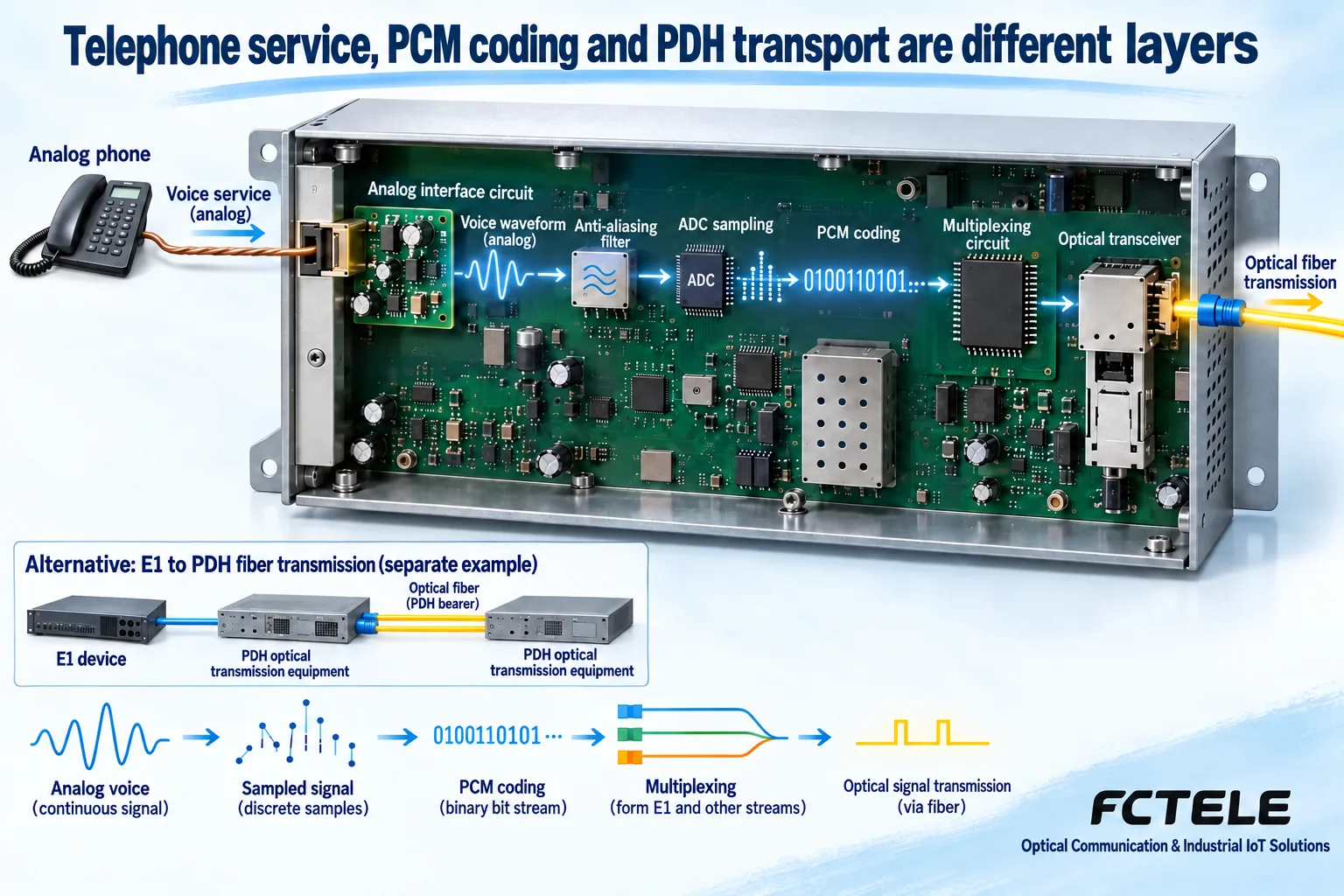
A telephone optical multiplexer is a device named after the telephone service it supports. PCM is a technology that samples, quantizes, and encodes analog signals. PDH describes a digital transmission system and its multiplexing layers. These three terms are not on the same classification dimension: one telephone optical multiplexer can include PCM encoding and may also use a corresponding digital line to carry the signal. They cannot simply be treated as three mutually exclusive types of equipment.
First, follow one phone call to see what each layer does
An ordinary analog telephone sends voice and related signaling over the line. The access device needs to identify the interface role, handle on-hook/off-hook and ringing, and then convert voice into information suitable for transmission. At the far end, the device restores voice and signaling according to the corresponding rules, so the telephone at the other end can work normally.
The name telephone optical multiplexer tells us the service goal, but it does not explain all the internal technology. When purchasing, you still need to ask about the telephone interface, number of channels, signaling, optical standard, and whether it is used as a set. Writing only “telephone optical multiplexer” cannot guarantee that the existing PBX, ordinary telephones, and lines are all compatible.
PCM answers how voice is digitized
Sampling is taking values over time. Quantization is dividing values into a finite number of levels. Encoding is expressing those levels as bits. For example, G.711 telephone encoding uses 8,000 samples per second and 8 bits per sample, giving 64 kilobits per second per channel. This describes the service rate of one encoding method, not the total capacity of an entire multiplexer.
Multiple PCM channels can be arranged into their own positions through time-division multiplexing, and the receiving end extracts them by channel. If the channel mapping is wrong, cross-talk may occur. If encoding or signaling is incompatible, the result may be unclear audio, failure to ring, or failure to release properly. Digitization does not mean ignoring interface roles.
PDH answers how digital lines carry signals in layers
PDH belongs to digital transmission systems and involves hierarchical rates and multiplexing. Interfaces such as E1 carry digital information in specific solutions, and it is also necessary to distinguish the physical electrical interface, frame structure, clocking, and service allocation. One E1 interface does not directly equal a complete product with a fixed number of telephone channels.
Some telephone equipment connects to other equipment through E1, while some uses a matching optical line format. Even if both sides say PDH or PCM, that does not prove their optical ports and service ports will naturally interoperate. You must compare the documentation layer by layer, rather than judging price or sophistication by the three terms.
FXS and FXO determine where the telephone connects
FXS provides the conditions required by an analog subscriber line, while FXO faces such a line. An ordinary telephone usually connects to a port that provides FXS capability. When the PBX side already has FXS, the matching access end often uses FXO. In practice, the PBX and equipment documentation should be taken as the standard; the RJ11 shape cannot replace role judgment.
Two-way voice also requires verifying call setup and teardown. You cannot only test whether sound comes out of the handset. Caller ID, dialing method, and other extended functions should also be clearly stated as supported or not, to avoid expanding basic call success into all telephone functions being available.
30 telephone channels on E1 is one configuration, not the upper limit of all equipment
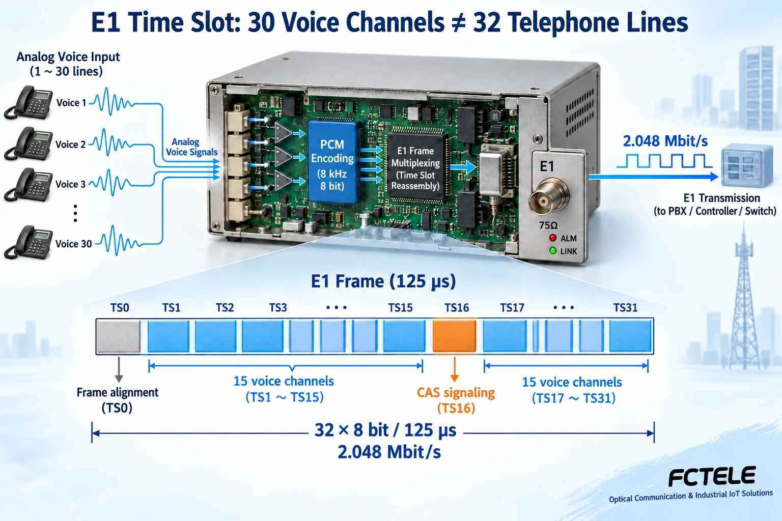
The E1 line rate is 2.048 Mbit/s. A common framing structure has 32 time slots per frame, and each time slot corresponds to 64 kbit/s. In a traditional telephone configuration using channel-associated signaling, time slot 0 carries information such as frame synchronization, time slot 16 carries signaling, and the remaining 30 time slots carry voice. This is the common source of “one E1 carries 30 telephone channels.” You cannot simply say that two time slots are only used for “signaling and clocking,” nor can you treat 30 channels as the capacity upper limit of all PCM equipment. The framing method, signaling scheme, service allocation, and equipment support must also be checked in detail.
For example, when both ends already have a matching E1 line, you can choose multiplexing equipment that maps analog voice channels to E1. When there is only optical fiber and no existing E1 interface, you need to confirm how the telephone optical multiplexers at both ends are paired to carry the service. Whether multiple E1, Ethernet, or other services can be transmitted at the same time is determined by the equipment structure, not by the word “PCM.” Physical line clocking, frame synchronization, and voice time-slot mapping should all be accepted separately.
When comparing products, list service ports first, then transmission ports
The service side of a telephone optical multiplexer usually faces telephone lines directly, while a PDH optical transmission device may use an E1 digital interface as the service entrance. If a project needs to extend ordinary telephones to a remote site, you cannot assume that telephones can be plugged in directly just by buying equipment with an E1 port; corresponding telephone access and signaling processing are also needed. Conversely, existing E1 services cannot be judged as connectable based only on the name telephone optical multiplexer.
The number of telephone channels, number of E1 ports, Ethernet rate, polarity reversal billing, caller ID, and protection circuits listed in old materials are all product capabilities that must be verified by specific model. They are not common properties of the entire category of equipment. You cannot infer from the use of PCM that three-level protection, completely noise-free operation, or maintenance-free operation is guaranteed, nor can you assert that other voice transmission solutions are all unstable. Put the interfaces at both ends, signaling, encoding, clocking, optical line compatibility, and simultaneously running services into a checklist, then select based on the manual and on-site testing.
Supplementary standards:ITU-T G.704 framing structure. The time-slot allocation above is an example of a traditional E1 telephone configuration and does not mean all equipment uses the same configuration.
Fill in these items separately when selecting
Clearly write the equipment at both ends, telephone interface roles, number of voice channels, concurrency requirements, and existing digital lines, then write the fiber type, distance, and installation environment. If E1 is used, note the framing, clocking, and channels. If a matching optical port is used, request compatibility and optical power documentation.
During acceptance, check incoming and outgoing calls, ringing, on-hook, and two-way voice channel by channel, then perform concurrency and link recovery during a maintenance window. Record line errors and alarms. An optical port LED being on cannot replace telephone function verification, and it certainly cannot prove that clocking has been stable over the long term.
Further reading
ITU-T G.711 can be used to understand voice encoding,G.703 explains the physical electrical characteristics of the corresponding digital interface. Standard concepts and product configurations should be checked separately.
After understanding the layers of these three terms, you can say during consultation, “We need a certain number of analog telephone channels to be transmitted to a remote site over existing lines,” and then confirm the equipment solution. This is closer to a real project than asking “Which is better, PCM or PDH?” and it also makes it easier to form clear acceptance goals.
In Feichang’s product documentation, FCC-CS30 is an E1 CAS PCM multiplexer, while FCP-O30/FCP-S30 are paired telephone fiber transmission units. Their line interfaces differ. They cannot be interchanged simply because both are described as 30-channel products: check the E1 electrical interface, timeslots and signaling, or confirm that the telephone fiber units are a compatible pair.
Product verification references:PCM category;FCC-CS30;FCP-O30/FCP-S30;
Illustration note: the diagrams explain general mechanisms. They are not photographs of a particular model, installation wiring drawings or measurement records. Interfaces and capabilities depend on the ordered configuration and on-site acceptance tests.
Can a PCM multiplexer replace a PBX?
A PCM multiplexer can encode voice, handle the relevant signaling and organize channels, so it would be inaccurate to say that it performs no service processing. However, fixed port mapping or timeslot cross-connections do not automatically provide a PBX’s extension number management, dialed call routing or outside-line permissions. When extending an existing PBX extension, a common arrangement connects the PBX’s FXS subscriber port to a matching FXO interface on the local PCM unit; the remote PCM unit uses an FXS interface to connect an ordinary analog telephone. The existing PBX still controls the numbers and calls. If the project needs new extension numbers, calling rules or outside-line permissions, first provide the appropriate PBX or call-control system, then check the transmission equipment interfaces. A particular model’s hotline mode does not mean that every telephone port can dial every other port freely. Specify the upstream equipment, both ends’ FXS/FXO roles, existing numbers and permissions, required call relationships and signaling. Test ringing, two-way speech and hang-up release separately, rather than checking only the E1 synchronization indicator.
Translated from the Chinese technical article. Source first published: 2022-07-07. Source last revised: 2026-10-13T13:19:24+08:00. Read the Chinese source
