


When testing a digital signal optical transceiver, you should check whether input states accurately reach the corresponding outputs, and clearly measure response, loss-of-signal, and recovery behavior. A lit optical path indicator or fast main/backup switching is not enough to prove that all channels meet the business requirements. Before testing, first clarify the interface version and observation boundaries, so the results have comparable meaning.
1. Turn requirements into observable conditions
First list the direction, input type, normal and alarm states of each signal path, and how the receiving end should interpret them. Confirm whether it is a continuous state, a periodic pulse, or an occasional short pulse, because their test methods differ. If the control system only needs equipment running feedback, high-speed video or network throughput should not be used as evaluation indicators.
Under controlled conditions that do not affect real actions, connect using an allowed signal source or test contact. At the far end, first connect a matching test input or indicator load, and avoid directly connecting to a circuit that would start equipment. Record the models, power supply, configuration, and fiber conditions at both ends, so another person can repeat the test according to the record.
Apply open and closed states to each path one by one, and compare local recognition, remote output, and controller acquisition. Changing only one path at a time helps find channel mismatches and wiring errors; after that, test multiple paths changing at the same time to check whether the common terminal, power supply, and system acquisition show different behavior.
2. From where to where does response time go
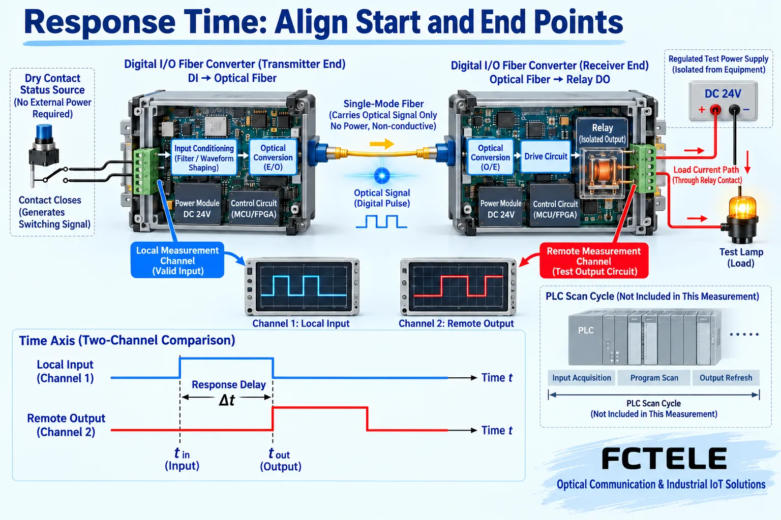
You can record the moment the input reaches the valid condition as the starting point, and the moment the remote output reaches the agreed valid state as the ending point. Between them are input recognition, filtering, transmission, receiving processing, and output action. If the ending point is taken from a controller record or mechanical action, the scan cycle, program, and actuator time are also added.
Different measurement boundaries cannot be directly compared. Relay pull-in and release may also differ, and software screen refresh time is even less equal to interface response time. When measuring with a dual-channel instrument, state the trigger threshold and output judgment conditions; record the range over multiple repetitions, and do not pick only the fastest single result as a guaranteed value.
The grounding method of instrument probes may change the original isolation. Use a suitable isolated measurement method, operate according to the instrument’s rated conditions, and do not clip an ordinary oscilloscope ground lead onto an unknown potential. When testing dry contacts, there should be an independent allowed test loop, and you cannot expect the contact to produce a voltage waveform out of nothing.
3. Will pulses be filtered out
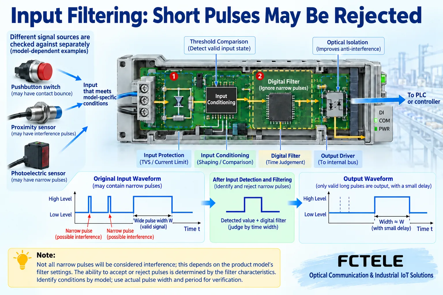
For pulse applications, check step by step the actual high and low level duration, repetition period, and input amplitude, and check whether the receiving end undercounts, overcounts, or sticks continuous pulses into one long state. The allowed conditions need to be defined by procurement materials, and then the behavior near that condition should be tested, rather than endlessly increasing frequency to find an accidental limit.
The Feichang FCP-K16G webpage lists optical backup switching specifications and digital signal interface parameters separately, and the interface forms are also different. The statement of optical path switching less than one millisecond cannot be directly written as the total response specification from all inputs to all outputs. The bit rate of an ordinary optical module also cannot replace input filtering and relay action capability.
4. Test main path failure and complete loss of signal separately
If the device has main and backup optical paths, interrupt the main path while keeping the input state stable, observe backup takeover, then restore the main path and check switchback. In a scenario where the input remains closed, check whether the output briefly opens; in a dynamic scenario, also check whether test pulses are missed. Before the operation, confirm that this test will not cause the real control loop to malfunction.
Then, in another test condition, make both paths unavailable, and record whether the output enters the preset state according to the specified strategy. A still-valid backup path and both paths completely broken are different conditions, and the continuous transmission result of the former cannot be extended to complete loss of signal. Device power loss is another situation, and the preset loss-of-signal state may not equal the contact position after complete power loss.
Power-on, optical path recovery, and restarting one end should all be checked. Record the conditions from loss of signal to valid output, whether recovery is automatic, whether manual confirmation is needed, and how the receiving system displays communication abnormality. Do not just write that recovery is “normal”; state the test state and observed result.
5. Stability should be recorded by time and count
For continuous-state tests, record the holding duration and the number of unexpected changes; for repeated-action tests, record the number of sends, number of receives, wrong paths, and missed actions. Zero abnormalities means no abnormality was found under this set of conditions and observation range, and cannot be written as zero failures forever. Changes in weather, load, power supply, and line route may all change the result.
For dual optical paths, check whether the routes are truly separated. If two fiber cores are in the same easily damaged cable, the device can switch but may not resist a single common cable break. Dual power supplies also require verifying the source and fault testing; seeing two input terminals does not mean power supply faults are necessarily independent of each other.
6. Which “optimizations” can be implemented on site
Give priority to handling loose terminals, incorrect input reference, contaminated optical connections, and mismatched loads. When filtering needs to be improved, the interface type changed, or backup added, handle it according to the supported configuration and product version. Users cannot arbitrarily change the modulation algorithm on site, add an EDFA optical amplifier, or apply network load balancing to improve contact transmission quality.
The acceptance table should include each path’s conditions, measurement boundaries, instruments, duration or number of actions, abnormal phenomena, and recovery actions. Keep the original records, and retest affected items after replacing sensors, output loads, or configuration. Only results obtained in this way can support delivery judgment and also provide a same-condition reference for later troubleshooting.
Sources: Feichang FCP-K16G product description;Feichang FCP-K1/2 product description;Feichang FCP-K4 product description;TI digital input module design materials;OMRON relay usage precautions;IEC 61000-4-5 surge immunity test description. The principle illustrations are general principle diagrams, belonging to general mechanism illustration, not product physical objects, measured waveforms, or certification documents.
Translated from the Chinese technical article. Source first published: 2024-08-19. Source last revised: 2026-10-13T12:16:42+08:00. Read the Chinese source
