


First determine where the error starts
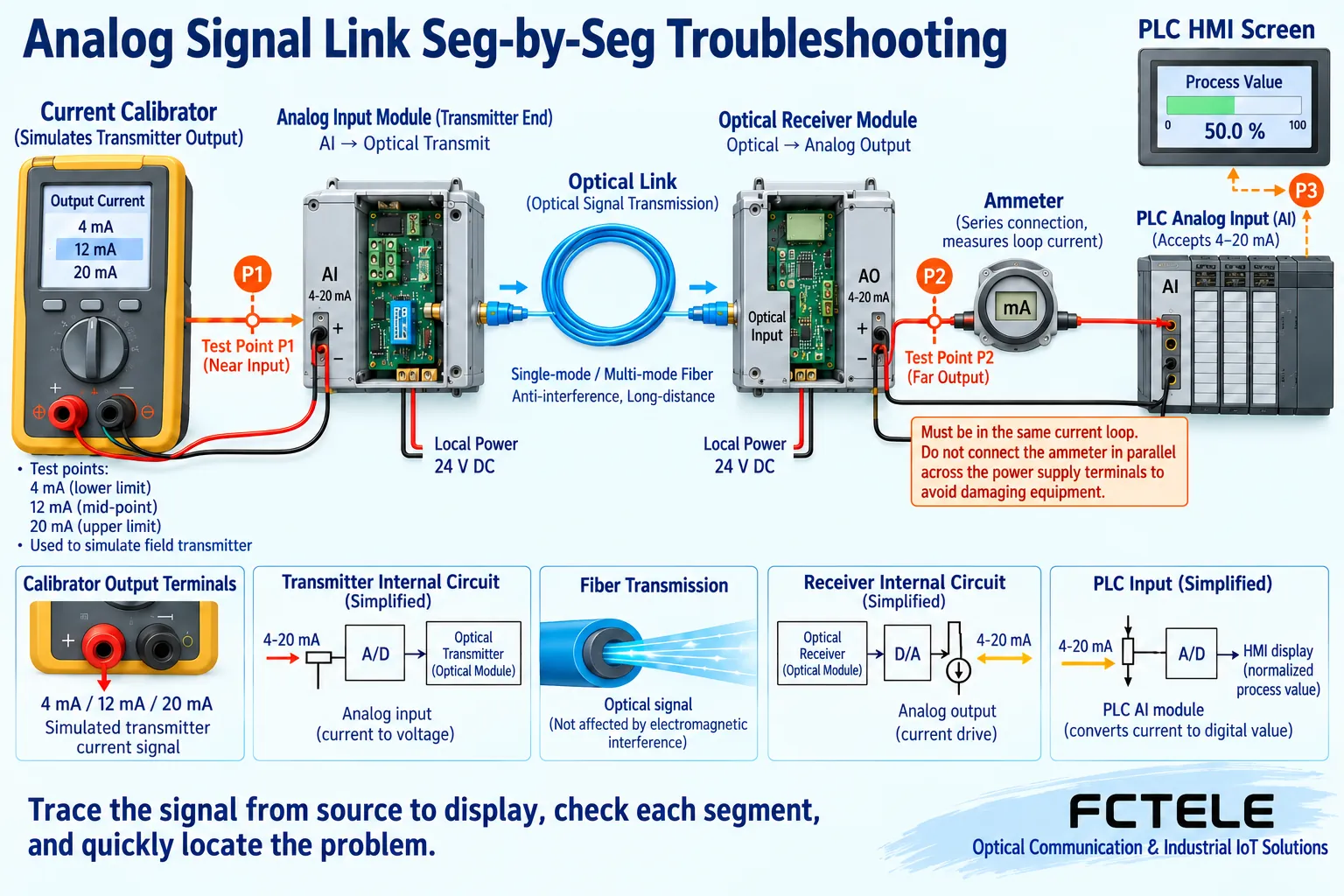
When an analog fiber optic transceiver shows no reading, value deviation, or a frozen display, first divide the link into five segments: signal source, near-end input, optical link, far-end output, and PLC. Here PLC means the controller that finally reads the measured value. Each segment must keep observable evidence so you can determine whether the sensor is not producing a signal, conversion is deviating, or the display rule is set incorrectly.
Before testing, record the original range, channel, output strategy, and alarm status. Arrange work according to on-site maintenance authority to avoid test current directly causing actuator action. You can check with an offline load or an approved maintenance state. Do not simultaneously replace equipment, adjust range, clear parameters, and rewire; otherwise, even if it temporarily recovers, it is hard to explain the real cause, and the fault may repeat later.
If there is no current, first check whether the loop is complete
A 4–20mA instrument may need loop power or may use independent power. Check whether the transceiver input provides the required power, the wiring role of the two-wire instrument, and whether the loop is closed. Do not judge that the sensor is powered just because the device working light is on. For a voltage interface, confirm the input range, reference terminal, and actual voltage; do not directly connect it the same way as a current loop.
To measure current, you need to insert a suitable ammeter in series under correct conditions; do not directly bridge the current range across the two ends of the power supply. To measure voltage, use the corresponding high-impedance voltage range. Operate according to the instrument instructions and on-site safety procedures. Without an electrical input, a normal optical link will not produce a correct measurement. Loose input terminals, reversed connection, or wrong interface type should all be ruled out before deeply modifying internal settings.
If the high end cannot go up, check load margin
If the middle point looks normal but the high end cannot reach 20mA, check the voltage margin required for current drive. The receiving load, line, and other series devices all produce voltage drop. When power is insufficient or the total load exceeds the allowed range, the output may saturate. The near-end transmitter loop and the far-end AO loop are two different circuits and should be confirmed separately; do not measure only one of them.
First, according to the instructions, replace with a known allowed load, compare the output under the same input, then check the power supply and related voltage drops. A voltage output with too heavy a load may also be low. Do not first amplify the scale in the PLC to make the reading reach the target and mask saturation; this will make the low end inaccurate and hide the real electrical problem. Any load replacement must be done under controlled conditions; do not arbitrarily short-circuit protective devices.
Five-point data can distinguish offset and scale problems
Use a matching signal source to provide 4, 8, 12, 16, and 20mA. After waiting for stabilization, record the actual near-end input, far-end output, and PLC display. If each point has approximately the same extra current, it may involve offset. If the deviation increases with input, it may involve scale, range, or gain. If it is low only at the high end, pay more attention to saturation and load. This describes troubleshooting clues; final confirmation still requires actual measurement.
Assume 4–20mA corresponds to 0 to 10 meters of liquid level; 12mA should be 5 meters. If the far end is indeed 12mA but the PLC shows 6 meters, first check whether the PLC mistakenly uses 0–20mA scaling. Verification with known signal points is not the same as unauthorized calibration. Only when the model provides corresponding adjustment steps and conditions are met should you execute according to specifications. Do not modify the range through an unknown menu and call the result a repair.
Jumping and slowness require different observation methods
When the value jumps, observe whether the near-end electrical signal is also jumping. If the input fluctuates similarly, check the sensor, power supply, terminals, wiring, or the real process. If the input is stable but the far end changes, continue comparing conversion, load, and link status. The optical fiber segment does not transmit via metal current, but this does not mean the copper wires and power supplies at both ends are immune to interference. Do not classify all problems uniformly as insufficient fiber interference immunity.
For slow response, consider input filtering, sampling, output refresh, and PLC scan. After filtering is increased, fluctuation becomes smaller but response time may also be lengthened. Use a controllable signal change to observe the time relationship and record the test tool and load conditions. Do not infer how long the final output takes to settle from the optical module rate. For pure analog terminal transmission equipment, do not treat adjusting the serial port baud rate as a default troubleshooting step.
Check optical path faults by pairing and power
Check the matching model, fiber type, optical interface, and transmit/receive relationship, and confirm the optical link according to the instructions. Use a suitable cleaning method for the end face. When necessary, use an optical power tool to measure and compare with the receive window. The plug being able to insert does not mean the service code is compatible, and receiving light does not mean the analog channel mapping is correct. Do not look directly into the optical port, and do not use naked-eye observation of whether there is light as a test.
First replace with a known-good short patch cord, keeping the equipment, input, and load at both ends unchanged. If it recovers, then check the connectors, splices, and loss in the installed optical path. If the short fiber also fails, continue checking pairing, optical module, and device status. When optical backup is needed, test the main and backup paths and switching separately according to the actual optional function. Do not directly treat the existence of a second optical port as meaning the fault has been eliminated.
A fixed reading may be holding an old value
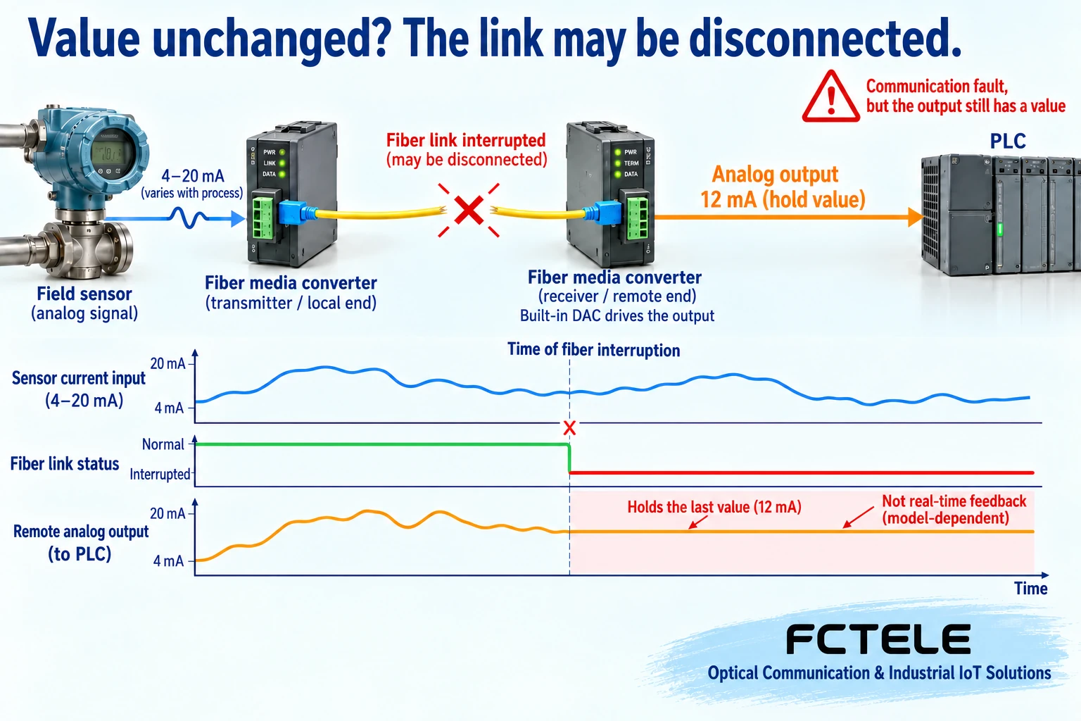
When the display does not change, first confirm whether the site is truly stable, then check whether input changes can reach the far end. Some devices hold the last valid output after a fiber break or transmitter power loss, so the PLC may continue to display an old value within the normal range. This phenomenon is completely different from normal output updating and must be judged together with link alarms or actual validity mechanisms.
The Feichang hybrid fiber optic transceiver details list a fiber break hold function that can be enabled through settings. During troubleshooting, check this status and the actual fault output. Hold value, zero return, or other settings all have applicable conditions; do not uniformly handle them without process analysis. Record the output and alarm after power-up, disconnection, and recovery, and confirm when new values begin to be accepted during recovery, to avoid old values being treated as real-time measurements for a long time.
After recovery, re-verify against the same baseline
After repairing a terminal, load, or optical path, re-execute known-point verification and save corresponding records before and after repair. If multiple channels are involved, change inputs channel by channel and confirm the far-end variables to rule out mis-mapping; also run channels that need to work simultaneously. During testing, do not take only one good-looking middle reading; cover the actual project range and allowed dynamic changes.
Finally, reconnect the on-site instruments, confirm that engineering values, alarms, and control logic are consistent, and check disconnection recovery under approved conditions. Hand over the model, range, power supply, load, optical power, output strategy, and measurement method to maintenance personnel. The completion standard for troubleshooting is to find the cause and prove the complete link has recovered, not that the light is on after the device restarts. Keep repeatable evidence so that the next abnormality can reduce blind replacement.
Data note: The principle diagrams have been checked against technical content and are used to explain general mechanisms. They are not product photos or actual measurement records. Specific interfaces, modes, and capabilities are subject to the selected model, version, and on-site verification.
Verification materials: Feichang analog product categories
Feichang hybrid fiber optic transceiver details and fiber break hold description
TI: Two-wire 4–20mA loop and voltage margin
TI: Difference between ADC resolution and accuracy
Related technical topics: How to choose an analog fiber optic transceiver: range, accuracy, refresh cycle, and optical path acceptance How FPGA analog-to-fiber works: channel scheduling, refresh cycle, and disconnection output What is the difference between discrete I/O and analog fiber optic transceivers: DI/DO, AI/AO, and wiring selection How analog fiber optic transceivers connect to industrial monitoring: PLC range, bidirectional channels, and disconnection strategy How analog fiber optic transceivers transmit signals: current voltage, ADC/DAC, and far-end output Can data fiber optic transceivers do interface and protocol conversion? Boundaries of serial port, analog, and Ethernet acquisition How analog video fiber optic transceivers differ from analog fiber optic transceivers: modulation, sampling, and measurement
Translated from the Chinese technical article. Source first published: 2024-05-07. Source last revised: 2026-10-13T11:52:05+08:00. Read the Chinese source
