


A fiber optic media converter connects an Ethernet electrical port and an optical port, solving the problem of transmission media conversion. When using it, first confirm that the optical specifications at both ends match, then connect power, network cable, and fiber, and finally verify the real service. An optical port light being on only means that some link conditions are met; it does not mean that the network segment, VLAN, and application configuration are all correct.
First draw a complete link clearly
Take a computer connected to a distant camera as an example: the near-end switch connects to the media converter through a network cable, fiber goes to the far-end media converter, and then a network cable connects to the camera. A media converter usually is not responsible for assigning an IP address to the camera, and it will not automatically bypass routing, authentication, or a firewall. It is only one part of the link.
If the far end is a switch with a compatible optical port, a second standalone media converter is not necessarily needed. But you must check the optical specifications, rate, wavelength, fiber type, and receive capability; “both sides have optical interfaces” cannot prove that they can interoperate. Fixed optical ports and pluggable modules also need to be confirmed separately for the actual configuration.
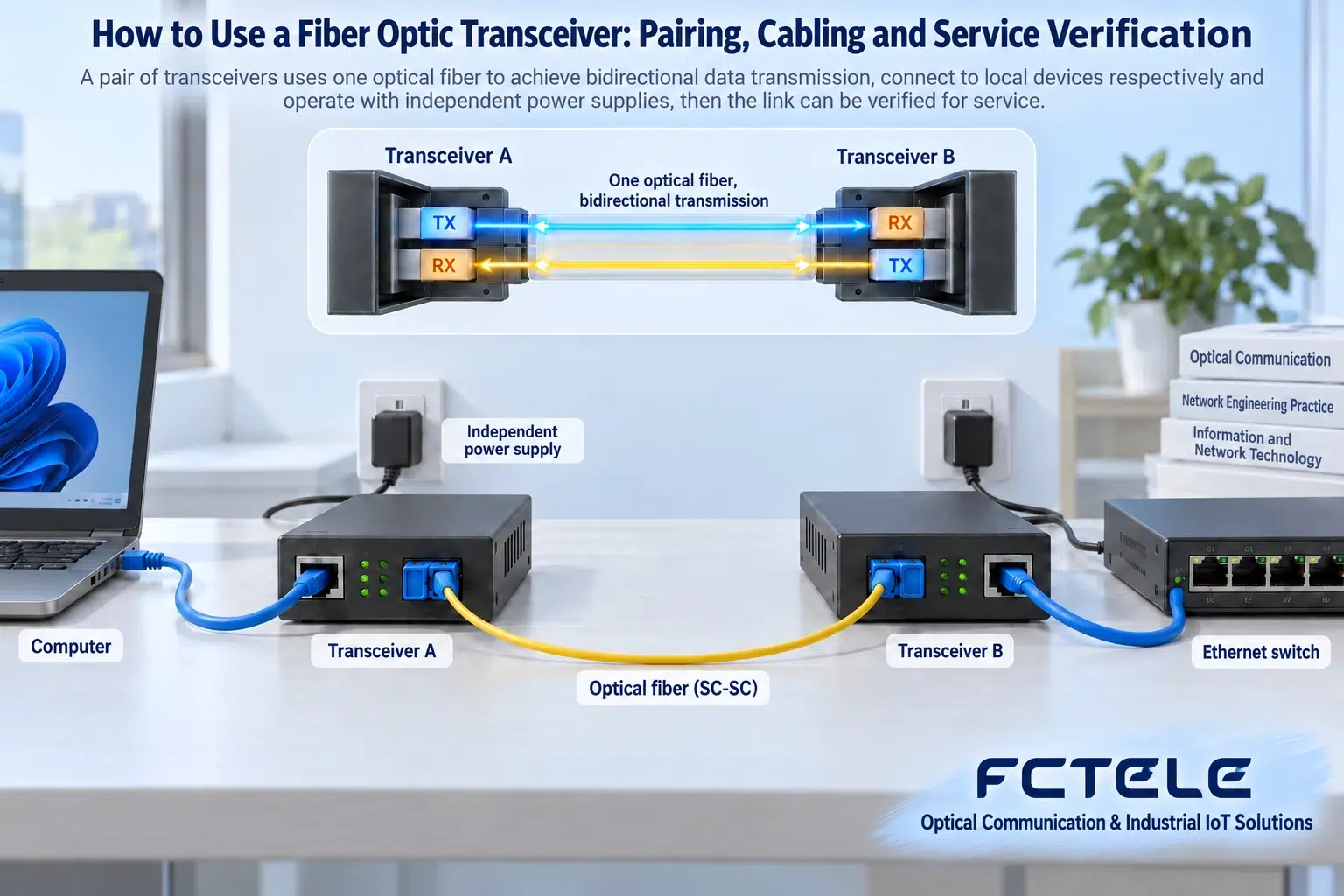
Dual fiber crosses, single fiber complements
A dual-fiber link uses two fiber cores. The near-end transmit TX must connect to the far-end receive RX, and the other core is connected in the reverse direction. Single-fiber BiDi uses different wavelengths to carry bidirectional signals over the same fiber core, and the transmit wavelength at one end must correspond to the receive wavelength at the other end. A and B are only pairing labels and cannot be judged without the manual.
Single-mode and multimode, and 100M and 1000M, cannot automatically become compatible just by changing a connector. You should also compare maximum transmit power, minimum transmit power, receive sensitivity, and overload conditions; it is not that the larger the nominal distance, the better. A link that is too short may need its received power handled according to the manufacturer’s recommendations, and you must not use random bending of the fiber to create attenuation.
Details easily overlooked during wiring
Before installation, check the power supply voltage, polarity, power, and grounding requirements, secure the device, and leave space for heat dissipation. Keep the fiber end face clean, connect it promptly after removing the dust cap, and avoid small-radius bends, pulling, and connectors hanging under stress. Do not look directly at a working optical port, and do not bring an unknown optical port close to your eyes for inspection.
The network cable must meet the device rate and on-site cabling requirements. An RJ45 electrical port does not mean the device supports PoE; the electrical port of an ordinary media converter also cannot automatically supply power to any terminal. Whether remote power supply is possible, which port supplies power, and the total budget must be verified according to the specific model.
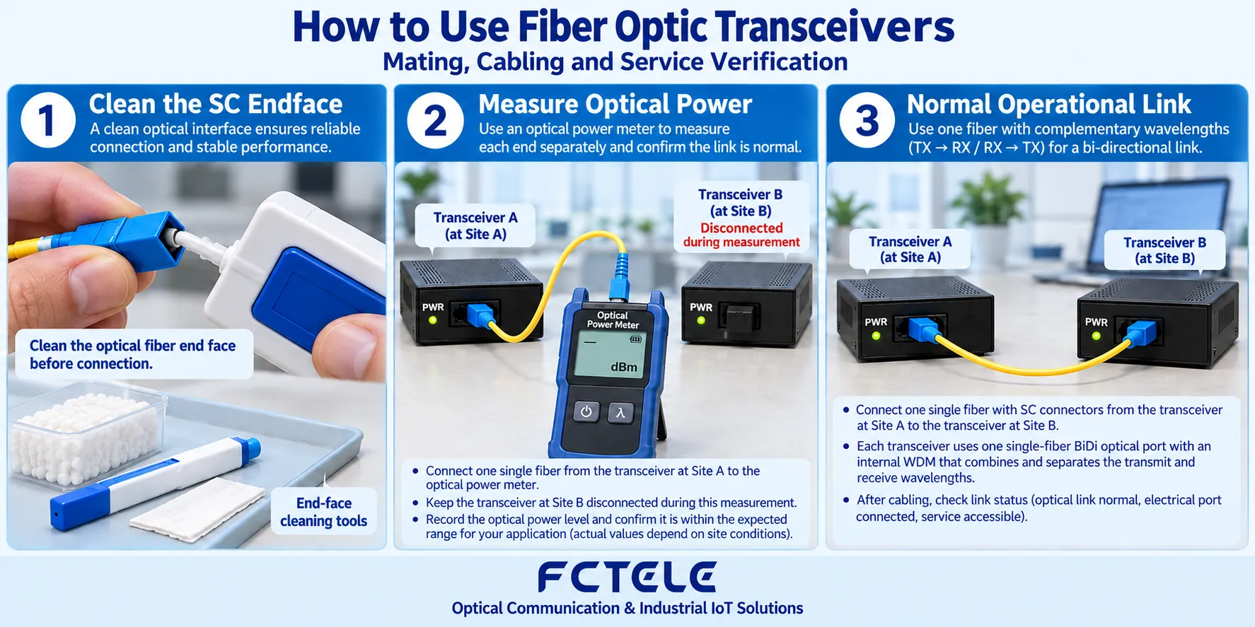
Why it still does not work after the lights are on
First check power and the link status at both ends, then verify the terminal IP address, subnet mask, VLAN, gateway, and application port. Different models may have different light names and blinking rules, so “all lights are on” cannot be treated as a unified normal standard. An activity light blinking often indicates traffic, but it does not directly prove that the traffic is the required service.
If only one-way service is abnormal, you need to distinguish between an optical link direction problem, a switch port policy, and application permissions. During troubleshooting, record which port shows CRC errors, packet loss, or link reconnection. First establish a short-link baseline, then gradually add the actual fiber and intermediate devices, avoiding changing multiple conditions at the same time.
Acceptance should test the camera, not just Ping
Ping is suitable for confirming basic network reachability, but it cannot represent that video bitrate, file transfer, and continuous operation all meet requirements. For camera projects, observe the actual picture, number of concurrent streams, recording continuity, and recovery process; for data projects, test the target application and expected traffic, and keep the measurement time and load conditions.
Power-off and link-disconnection tests will affect on-site services and should be performed during an approved maintenance window or on an independent test bench. After recovery, check address learning, application reconnection, and timestamps; do not just look at the link lighting up again. A qualified record should be able to explain where the fault occurred, how long the service was interrupted, and whether it recovered automatically.
Common questions
Can a media converter increase the rate of the original network port? It cannot be assumed so; the entire link is limited by the slowest interface and the actual carrying capacity. Can it directly replace an operator’s optical modem? An ordinary Ethernet media converter usually does not have PON access and operator authentication functions, and the two types of devices cannot be interchanged just because they have similar optical port appearance.
If you need to select a model, providing the devices at both ends, fiber type, actual length, and service traffic is more useful than only asking “how many kilometers.” You can combine Single-fiber A/B pairing instructions understand the complementary relationship, and then complete the matching according to the optical parameters of the specific product.
Translated from the Chinese technical article. Source first published: 2019-07-24. Source last revised: 2026-10-13T22:50:44+08:00. Read the Chinese source
