


Whether an industrial fiber switch connection is reliable depends on port and module compatibility, fiber transmit-receive pairing, endface cleanliness, and line loss. It is not guaranteed just because plugs of the same shape are inserted. This article explains the principles and acceptance of actual wiring and does not provide backend configuration commands for any specific model. Equipment power supply, grounding, and construction should be implemented according to the corresponding manual and site regulations.
Before wiring, first draw a complete data path
A common site link is: the terminal’s Ethernet electrical port connects to the switch, then the switch’s optical port connects to a remote switch or aggregation device, and finally reaches the server. When a terminal has no optical interface, you cannot directly plug a fiber into its RJ45 network port. Fiber mainly carries optical signals, and an ordinary optical link will not provide power to the site switch.
First write the purpose of each interface on the diagram: which electrical port connects to the camera, which optical port is the uplink, and which power supply feeds the site equipment. If the switch uses SFP modules, the optical-electrical conversion happens inside the module; for fixed optical port devices, check against their own optical interface specifications. The two end devices do not need to have exactly the same enclosure, but the optical port standard, rate, and optical conditions must be able to match.
Same connector type is only the starting point for verification
Names such as LC and SC mainly describe the connector structure; single-mode and multimode describe the fiber conditions; single-fiber and dual-fiber describe the number of fiber cores used. These items are related to each other, but one cannot replace another. For example, both ends having LC connectors does not prove that one gigabit optical port can receive data from another ten-gigabit optical port.
A dual-fiber link usually requires one end’s TX transmit port to go to the opposite end’s RX receive port, with the other fiber core carrying the reverse transmission. For single-fiber BiDi, check the complementary transmit and receive wavelengths and confirm that both ends are compatible specifications. The A/B labels can help with pairing, but you should not pair across series based only on letter combinations; write the complete model and wavelength into the wiring record.
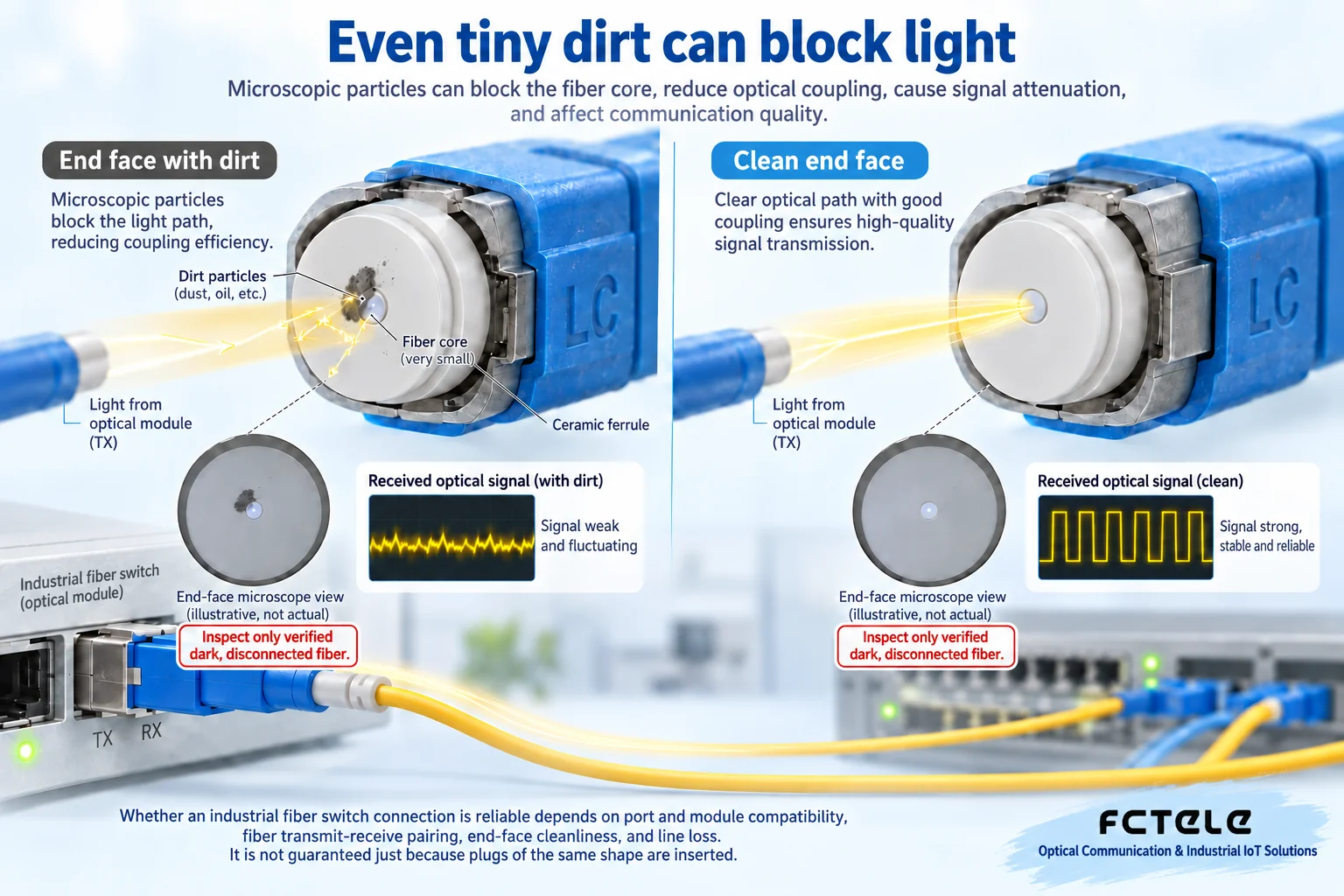
Why even a tiny speck of dust is worth dealing with
Fiber guides light into a very small effective area, and the connector endface needs to couple the optical paths on both sides precisely. If contaminant particles block a critical position, they may increase loss or cause endface damage during connection. Looking clean, just unpacked, or having always worn a dust cap are not sufficient evidence that the endface is qualified.
The correct approach is to use suitable inspection tools to confirm the endface condition, use a suitable cleaning method when needed, and then re-inspect. Do not wipe with clothing, fingers, or random solvents, and do not treat one wipe as permanently qualified. Specific tools, cleaning agents, and procedures should follow the connector and site regulations. Do not look directly into optical ports; especially, you cannot rely on your eyes to judge whether an invisible wavelength is emitting light.
Contamination not only affects one patch cord but may also transfer to equipment ports. Therefore, when an abnormality is found, consider both the patch cord end and the equipment interface. Without suitable inspection conditions, it is not advisable to repeatedly plug and unplug hoping for luck, and even less should you keep increasing transmit power just to make a light turn on. Optical power range and endface condition are two different types of problems.
When plugging and unplugging, hold the connector, not the module pull ring
The connector of a fiber patch cord and the pluggable optical module are two separate parts. When unplugging a patch cord, release the connector’s own latch, hold the connector body according to its structure, do not pull the fiber cable, and do not use the SFP module’s pull ring as a handle for pulling the fiber. The module pull ring is used for the release mechanism of the corresponding module; its specific direction and steps should follow the manufacturer’s installation instructions.
First understand how the latch works, then operate gently. Do not use brute force to solve ‘hard to pull out.’ Different connectors and modules vary in shape, so the diagram expresses the principle of distinguishing parts, not a construction action shared by all devices. When involving module removal and installation or live operations, also check the host manual and electrostatic protection requirements.
Optical budget is more specific than the marked kilometer rating
The optical power at the transmitter suffers fiber attenuation, connector loss, and splice loss along the line, and after reaching the receiver it must be within a range that can be correctly identified. A common calculation can be understood as transmit power minus total loss to get the estimated receive power, then retaining an appropriate margin. Transmit power and receive power are often expressed in dBm, and loss in dB; you cannot treat both as linear watts and add them directly.
Transmitting far does not mean it is necessarily better on a short line. In addition to sensitivity, the receiver also has an overload upper limit, and excessively strong light may also be unsuitable. If the line is very short but a longer-distance module with higher output power is selected, verify against the specifications at both ends rather than automatically assuming ‘the more margin, the safer.’ Two lines with the same fiber length may also have different actual losses because of different connection points.
Feichang Technology industrial switches have different copper and optical port combinations and installation forms. Actual ordering should confirm the host ports together with the matching optical modules and patch fibers. A certain series offering a certain type of module does not mean all devices of the same brand support the same optical port rate, wavelength, or distance. Submitting project conditions to the manufacturer for verification and obtaining clear specifications is more effective than reporting only a kilometer figure.
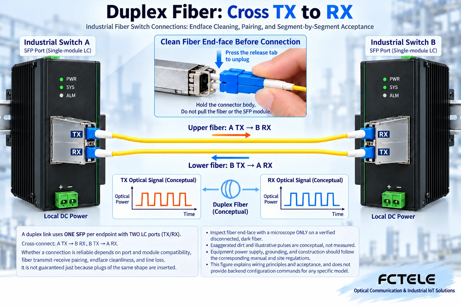
First establish a short-link baseline, then connect the actual line
In a permitted test environment, you can use a known-good, clean, and compatible patch cord to establish a short link and confirm that the devices and modules at both ends basically work. Then connect the actual cabling and compare port status, received optical power, and error counters. This can distinguish whether the problem is in the device combination or in the line portion, rather than replacing all parts at the same time.
Seeing the optical port light on is not enough. It usually reflects the connection status at a certain layer, and services may still be affected by VLAN, address, multicast, or application settings. First confirm the physical link, then check the switching forwarding scope and terminal services, to avoid blaming everything on the fiber. The instructional diagram does not provide commands for unknown models, nor does it replace Feichang Technology’s actual firmware with another vendor’s configuration menu.
If received power is abnormal, check fiber type, wavelength, pairing direction, endface, and line loss; if power and link status are normal but data is still unstable, further check bit errors, drops, port negotiation, and uplink load. Change only one main condition at each step and keep the before-and-after results, so troubleshooting has a chain of evidence.
At the end, leave clear records for the next maintenance person
Clearly mark the device models, module specifications, port numbers, patch cord numbers, and transmit-receive directions at both ends, to avoid mistakenly swapping a pair of fiber cores during the next maintenance. Cabling should leave appropriate slack and meet the minimum bend radius requirement; do not crush or fold it, and do not subject connectors to continuous stress. Organizing excess cable should not involve tightly winding the fiber into a very small coil just for appearance.
Finally, verify transmission and alarms under actual service load, and record installation location, time, optical power, and version information. If the project includes redundant paths, switching should also be tested according to a dedicated acceptance plan; you cannot temporarily ‘enhance reliability’ by connecting a loop. Clean endfaces, correct pairing, a clear budget, and traceable records together form a reliable optical link.
Verification materials:Cisco optical module installation guide;Feichang Technology industrial switch categories. The principle diagrams are used to explain general mechanisms and are not measured diagrams or wiring diagrams for specific models.
Translated from the Chinese technical article. Source first published: 2023-10-27. Source last revised: 2026-10-13T20:37:04+08:00. Read the Chinese source
