


When an industrial switch has a fault, first separate device power, physical link, data forwarding, and the final application. A link light being on does not mean the business is definitely normal, and a business failure does not necessarily mean the switch is damaged. Preserving the on-site state and changing only one condition at a time is usually easier for finding the cause than repeatedly unplugging cables and restoring factory settings. Specific configuration operations should still follow the manual for the corresponding model.
First record the fault scope, rather than immediately restarting all devices
First ask whether it is one terminal failing, one area failing, or the whole system failing; whether it is a complete interruption or occasional stuttering. Record the time it occurred, affected devices, indicator lights, power status, and recent changes. If the abnormality always appears when a certain device starts, the power or traffic change during startup may be more worth checking than “the switch is broken.”
A restart can sometimes temporarily restore service, but it may also clear error counters and on-site evidence. Randomly cutting power in a production network can also expand the impact. You should first record the state within the allowed scope, then decide whether to perform a controlled restart; for each operation, write clearly what was changed and what the result was. You cannot simultaneously replace a cable, replace a power supply, and change an address, and then assert that one of those steps must be the cause.
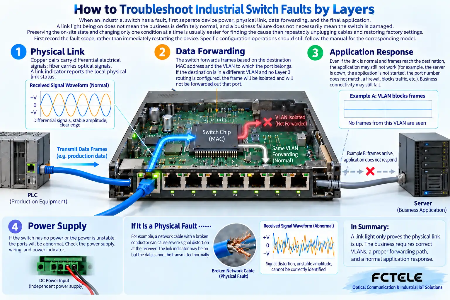
The first layer is power and physical link
The switch needs a stable power supply that meets the model requirements. When a device occasionally restarts or all ports disconnect at the same time, check the power supply and load changes, not only the data cable. The rated parameters of a power supply are not equal to the voltage actually obtained on site; poor contact and line voltage drop can also cause problems. Live checks should be completed by qualified personnel according to safety requirements.
Copper cable links should be checked for rate, cable, and termination; optical links should be checked for module, fiber type, wavelength, connection method, and receiving conditions. Dual-fiber connections require the transmit port to go to the opposite end’s receive port, and single-fiber devices require the corresponding wavelength combination. You cannot assume the entire optical interface is compatible just because the connector can be plugged in; when checking fibers, you also must not look directly at the end face with your eyes.
A link light being on only answers part of the question
A link light usually reflects certain states of the physical connection, but it does not prove that data definitely enters the correct network. The switch also decides forwarding based on addresses and the network scope to which they belong. VLANs divide the Layer 2 network into different scopes. If a terminal is placed in a position that does not match the design, the physical link can be normal, but the business may still be unable to reach its destination.
The terminal’s IP address, mask, gateway, and application service are another layer of conditions. Being able to access the switch management page does not prove that camera video can reach the recorder; being able to Ping does not prove that a specific application port and business are continuously normal. During troubleshooting, record “interface connected,” “network path reachable,” and “actual business successful” separately, to avoid expanding one test conclusion to the entire system.
Do not treat forced low speed and full duplex as a universal fix
Speed and duplex mode should match the devices at both ends and the link conditions. Some faults involve negotiation or compatibility issues with legacy devices, but this cannot be used to recommend forcing all ports to a certain speed and duplex mode. Mismatched settings at both ends may introduce new problems, and lowering the rate may also hide cable defects and turn an originally sufficient uplink into a bottleneck.
If you suspect a negotiation problem, first record the current state and error counters at both ends, check the supported methods of the corresponding devices, and then make changes under authorized test conditions. After the change, verify data traffic and business, and keep the original settings for restoration. You cannot declare the repair successful just because the link light comes back on.
Why egress congestion causes stuttering and packet loss
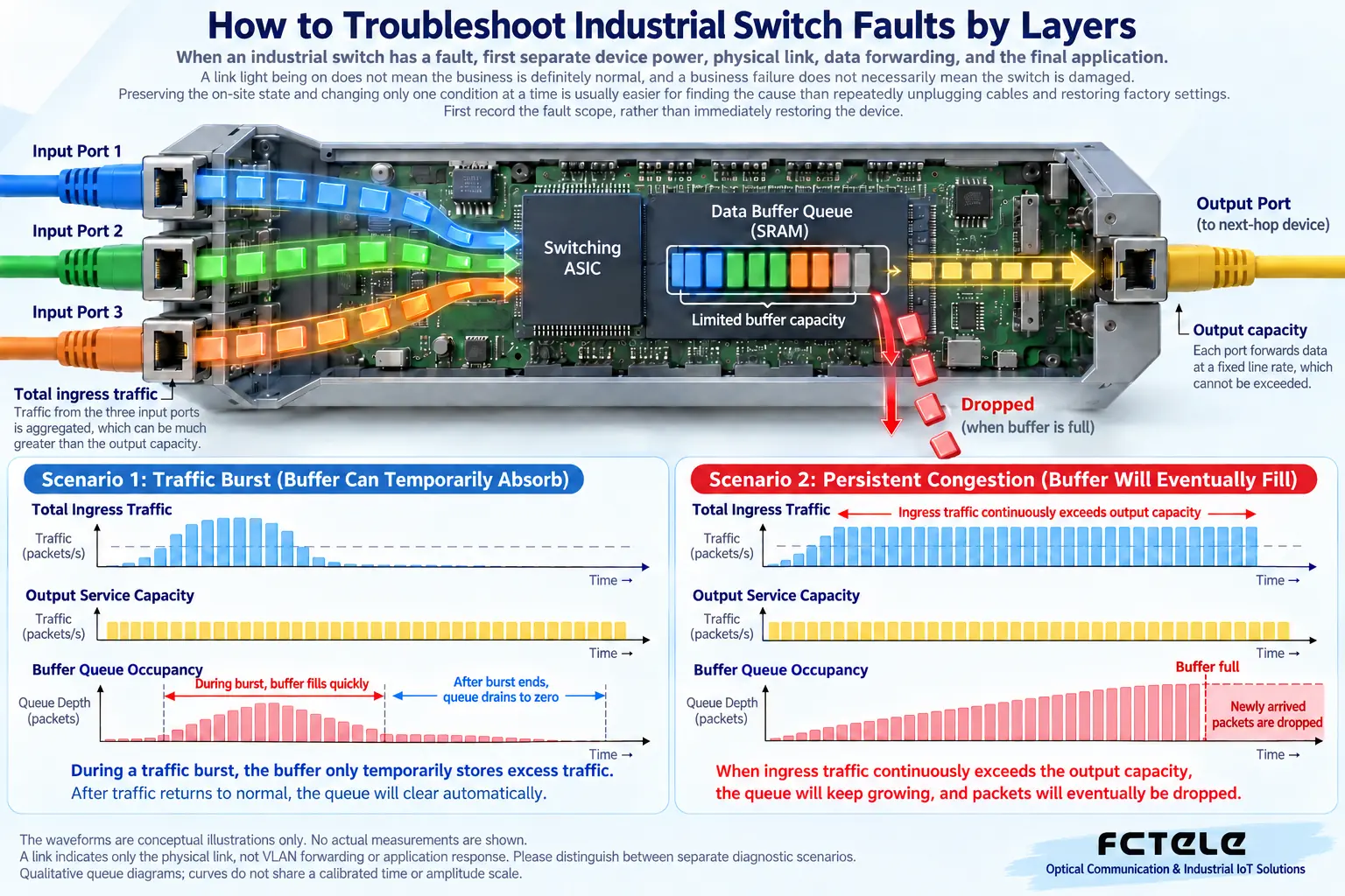
When data from multiple inputs is preparing to pass through the same egress, the switch may place data that cannot be sent in time into a queue. A queue is like a waiting area, but its capacity is limited. If the input continues to be faster than the egress sending capability, the waiting area keeps growing and may eventually discard data. Buffering can only absorb short bursts to a certain extent; it cannot create bandwidth that is lacking for a long time.
For example, when multiple video streams pass through a certain uplink in a concentrated way, that egress bears the aggregate traffic actually passing through it. Other ports on the switch still having margin does not mean this egress also has margin. You need to observe the path, port traffic, and discard statistics when stuttering occurs, rather than only comparing the device’s advertised total switching capacity. Short bursts may also cause queue pressure even when the average traffic is not high.
Increased broadcast traffic is not necessarily all loops
Broadcasts are sent to multiple ports within the corresponding network scope. Normal activities such as device discovery and address resolution may also generate broadcasts, so seeing broadcast counters and judging it as a loop is not accurate. On the other hand, a physical closed loop lacking correct control may indeed cause Layer 2 frames to be forwarded repeatedly, causing a large amount of duplicate traffic and interfering with normal business.
It should be judged together with topology changes, error symptoms, and related statistics. Ring network or spanning tree functions require device support and must run according to the design; you cannot regard several cables forming a circle as reliable redundancy. Handling should follow the confirmed topology and maintenance process, avoiding arbitrarily unplugging links that carry critical business. This article explains the judgment relationships and does not replace specific network configuration documents.
Industrial environmental issues should be separated from network mechanisms
High temperature, poor ventilation inside the cabinet, power disturbances, and loose connectors can all affect device operation; these problems cannot be solved through VLANs or address settings. Fanless does not mean no heat is generated, and a metal enclosure does not mean heat can be removed from any installation position. You should check the allowable conditions for the specific model and observe the actual environment inside the cabinet.
Dual power inputs also do not automatically mean independent redundancy: if the two paths come from the same fault point, they may still fail at the same time. Checks of grounding, surge protection, and power should follow project design and safety requirements, and you should not “eliminate interference” by removing protective grounding. Industrial attributes, network redundancy, and electrical protection are different capabilities and must be verified separately.
How Feichang Technology managed models assist in locating faults
The Feichang Technology 2307 official website details related management and STP, RSTP, and other functions, and you can check monitoring and redundancy requirements according to the actual configuration. Management capabilities help view status and narrow the scope, but available counters, pages, and functions should still be based on the actual model and firmware; you cannot assume that all Feichang Technology industrial switches have the same interface.
When selecting equipment, you can list the required diagnostic information as a checklist: whether port status, traffic statistics, logs, and related protocol status are needed, then confirm each item using the product details and manual. Diagnostic functions provide evidence and will not automatically eliminate all on-site faults; equipment selection and on-site design still need to work together.
An example of troubleshooting one single controller going offline
Assume only one controller intermittently goes offline, while other terminals are normal. You can first save the port status and controller power records, then, under allowed conditions, replace and test with a known-good cable. If the problem remains, continue observing controller restarts, address conflicts, and business services, rather than directly resetting the entire switch.
Each step should record the difference before and after, and finally verify continuous operation with the original business and check whether new alarms appear. This can both explain the cause of the fault and form a reusable maintenance record. The standard for repair is not “the light is on,” but that the corresponding business recovers under the agreed operating conditions and the related abnormal evidence is explained.
Reference materials:Feichang Technology managed industrial switches;Ethernet switch mechanisms. The diagram explains general mechanisms and is not a wiring diagram for a specific model.
Translated from the Chinese technical article. Source first published: 2019-07-19. Source last revised: 2026-10-13T20:54:09+08:00. Read the Chinese source
