


The performance of an industrial optical Ethernet switch cannot be proven by a port showing gigabit or by a single speed test result. First determine which port the data enters and where it exits, then distinguish port rate, forwarding capability, and application performance. Optical ports solve the problem of transmission medium and distance; they do not automatically make same-rate services faster than electrical ports. This article provides a repeatable testing approach. All calculation examples are for explaining the measurement basis, not actual test reports of Feichang Technology products.
First draw the test path and find out who might limit the result
Take two computers transferring a file through a switch as an example. The data must pass through the application, the host protocol stack, the network card, the cable, the switch, and the receiving end. Computer processing power, storage speed, operating system, and TCP settings can all limit the result. A lower speed measured between two computers does not directly prove that the switch’s forwarding capability is insufficient; similarly, a single connection working normally does not prove that there is no bottleneck when multiple ports work together.
Create a topology record: write down port numbers, negotiated rates, duplex modes, optical module models, cables, VLANs, aggregation, and rate-limiting settings separately. Optical modules must match the interfaces at both ends. If there are link error counters, handle physical layer problems first. Keep configurations consistent for each comparison, and record instrument and host versions; do not attribute all improvement after changing cables, modules, and configurations at the same time to a single action.
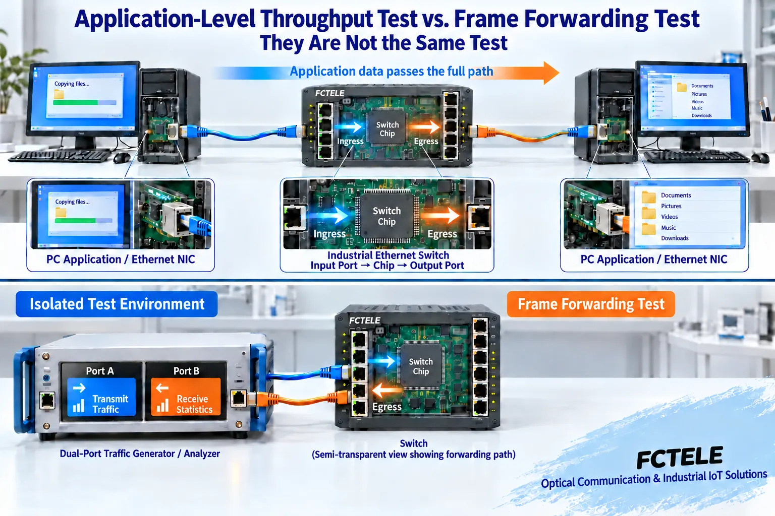
Port rate, application throughput, and frame processing answer different questions
Port rate describes the link transmission capability; application throughput counts the effective data actually received by the application. Ethernet frame headers, checksums, inter-frame gaps, and upper-layer protocols all consume transmission resources, so application values usually do not equal the port’s nominal value. Gb/s means how many bits per second, MB/s means how many bytes per second. Before comparing, unify the units and state whether only the payload is counted.
A 1 Gb/s full-duplex port can work at the negotiated rate in each direction. Adding the results of the two directions gives the bidirectional total, but it cannot be written as a single direction exceeding 1 Gb/s. An old article’s “1.2 Gb/s measured” without topology, direction, and measurement basis cannot be used as evidence for selection. Link aggregation also requires explaining hash distribution and flow count; the total of multiple flows cannot be used to promise that a single connection can reach the same speed.
Small frames mean that at the same bit rate, the device needs to process more frames per second. Switching capacity focuses on total bit traffic, while packet forwarding rate focuses on the number of frames processed; testing should cover different frame sizes, not just transfer large files. For the specific calculation method, see Capacity and Packet Forwarding Rate Calculation, and the test report should also state whether link overhead is included.
Do laboratory benchmark testing and on-site acceptance separately
In the laboratory, a traffic tester can be used in an isolated network to generate known data frames and compare sent volume, received volume, timestamps, and sequence numbers. Throughput, frame loss, and latency should be measured under the same configuration, frame size, flow direction, and load basis. Set duration, number of repetitions, and stop conditions, and keep raw records; do not just take the best result.
On-site acceptance focuses on services: whether control messages arrive on time, whether video is complete, whether alarms are timely, and whether communication recovery meets the agreement. Host speed test tools can serve as end-to-end application checks, but the path they measure is different from the frame forwarding benchmark of dedicated instruments. Benchmark testing may intentionally push resources into congestion and should be placed in an isolated environment; do not move high-load experiments directly to a running production network.
What latency is measured should be written next to the result
Ping usually observes round-trip response and also includes host processing and device response behavior; it does not equal the one-way forwarding latency of a switch. One-way measurement must state time synchronization, timestamp location, and instrument accuracy; store-and-forward devices are also affected by frame size. A mean value cannot represent all packets. When necessary, record distribution, variation, and abnormal moments, but do not promise a uniform microsecond or millisecond upper limit without basis.
Before testing, the business side should provide the criteria. For example, alarm services care about the maximum acceptable arrival time, video services care about frame loss and completeness, and file synchronization cares more about effective throughput. Comparing measured values with this service criterion is what makes acceptance meaningful. If different devices’ charts have different measurement points, frame sizes, or background traffic, they should not be directly ranked.
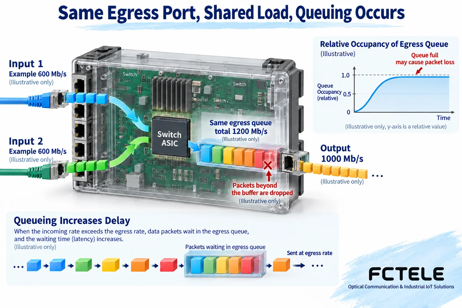
Use actual flow directions to verify multi-port and feature loads
Multiple cameras to the same recorder will concentrate on the same egress; multiple unrelated port pairs may be distributed across different egresses. With the same total ingress traffic, the congestion location can still be completely different. Record the load, errors, and drops of each egress to avoid using a whole-device average to hide local congestion. QoS is queue scheduling during congestion and does not create additional link bandwidth.
If the service requires VLAN, multicast, or Layer 3 routing, testing should use the corresponding configuration, not just test in factory default mode and then deliver. Multicast checks joining, leaving, and actual receivers; routing checks the required addresses and policies. Security policies, mirroring, and rate limiting should also state whether they are enabled; a feature being listed in the documentation does not mean it has the same result under any combination.
Redundancy and environmental verification: focus on services, not promotional numbers
For a ring network test, first confirm that there is no loop forwarding during normal operation, then create a specified link failure under controlled conditions. The topology change time in device logs and the application recovery time may differ and should be recorded separately. Do not directly convert a protocol name into a fixed recovery time; the number of devices, detection method, configuration, terminal cache, and service timeout all affect the result.
Environmental testing should be carried out by appropriate personnel and facilities according to model conditions. Temperature, humidity, installation method, power supply, and module combination should all be written into the report. Do not treat connectivity at any high temperature as a formal qualification test. Maintain a service load similar to the site, observe port errors, alarms, and service continuity, and set stop conditions. The conditions in an inspection report cannot be extrapolated to mean unlimited stability in all scenarios.
Turn Feichang Technology product features into test items
Feichang Technology Managed Industrial six 10-Gigabit optical ports plus 48G Optical-Electrical Swappable Layer 3 Switch The documentation lists port statistics, system logs, SFP module information, VLAN, IGMP, and various ring network features. During procurement, inspection items can be drafted based on these and accepted item by item according to the delivered modules, firmware, and configuration. If the packet forwarding rate unit in public parameters is ambiguous, request the exact unit and test conditions; do not change it yourself into an assumed performance number.
Delivery results should include topology, prototype identity, configuration files, instrument basis, load, environment, raw counts, and criteria. List passing and failing items separately; only repeatable anomalies are convenient for correction. A “comprehensive evaluation” without this information is only a description and cannot replace reviewable performance evidence.
For the scope of test methods, see RFC2544 and RFC6815. For the scope of application speed test tools, see also ESnet iperf3 documentation. This article independently explains the measurement objects and does not provide any actual product test conclusions.
Translated from the Chinese technical article. Source first published: 2023-10-26. Source last revised: 2026-10-13T17:37:33+08:00. Read the Chinese source
