


Installing an industrial switch starts with securely fixing the device in a suitable environment; connecting cables comes second. DIN rail, wall mounting, rack mounting, and desktop placement are different mechanical solutions, not random ways to place the device. This article explains the relationships among support, locking clips, cable pulling force, and heat dissipation to help first-time installers understand why it is done this way. For power and optical port wiring, see the separate wiring topic.
1. Choosing an installation method: first check whether the device and location match
First confirm the installation accessories the switch supports, then confirm what kind of support structure the site has. Rail-mounted models are usually suitable for control cabinet DIN rails; wall-mounted models need matching mounting ears or mounting plates; rack-mounted models need a corresponding rack and fixing components. Desktop placement is only suitable when the device allows it, the environment is stable, and it will not be bumped or pulled. Do not stuff an unfixed desktop device directly next to vibrating equipment.
Even when something is also labeled “DIN rail mounting,” the hooks and locking clips on the housing may be different. The DIN rail dimensions, direction, and accessory model numbers marked in the manual should all be checked before installation. Do not copy general load-bearing numbers, how many turns to tighten a screw, or claims such as “terminals must face up” from older articles. Load-bearing capacity and direction depend on the device structure, accessories, DIN rail fixing, and on-site vibration conditions; they are not decided by a universal saying.
2. How a DIN rail transfers weight to the cabinet
Imagine hanging a hook on a horizontal bar: the weight is not carried by the network cable, but is transferred along the housing, mounting parts, DIN rail, and DIN rail fixing points to the cabinet. A common spring locking clip structure first lets the fixed hook catch one side of the DIN rail, then presses the other side toward the DIN rail so the locking clip catches the other edge. The locking clip limits detachment and, together with the hook, forms stable support.
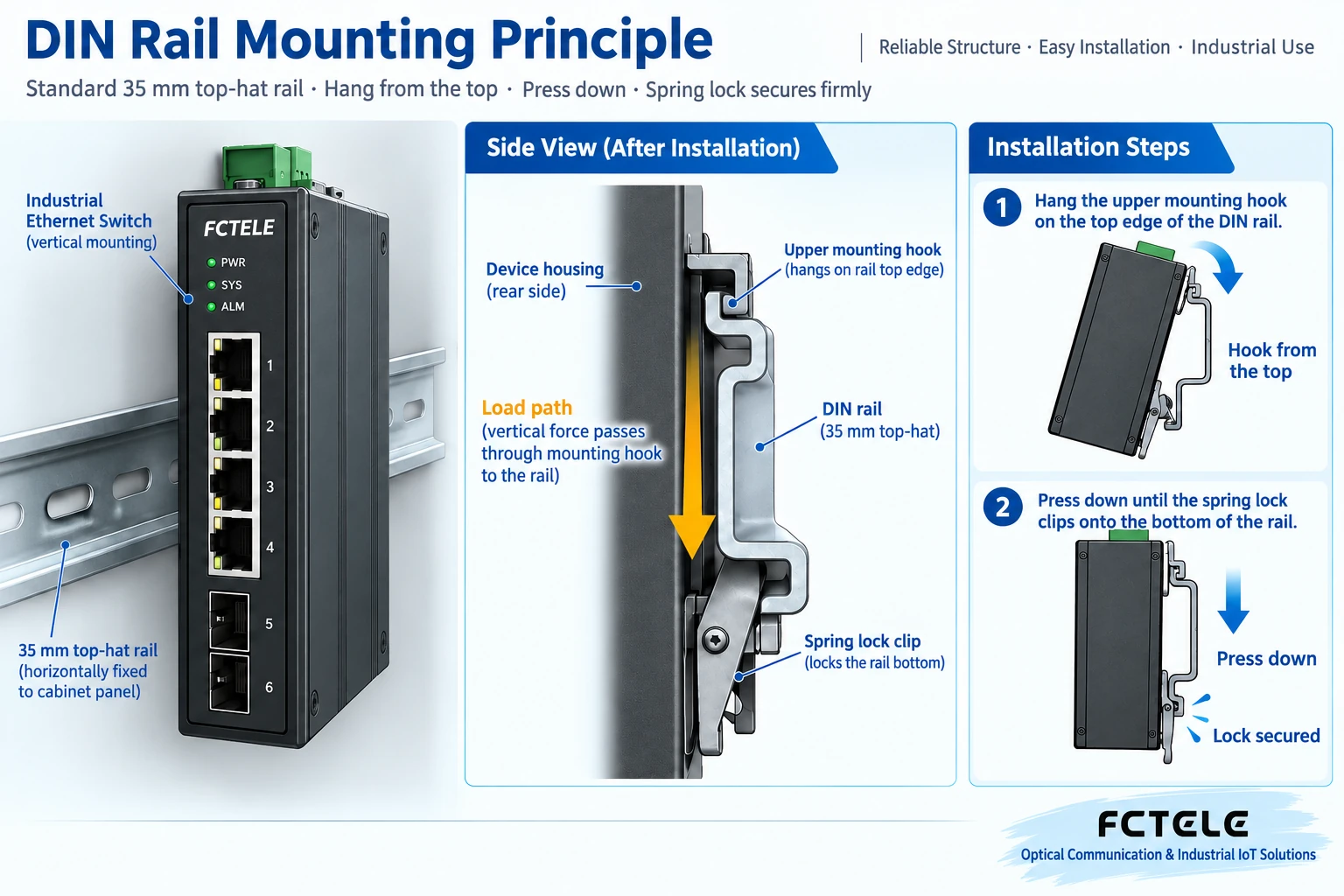
Before installation, check whether the DIN rail is secure, whether the backplate is deformed, and whether the mounting part screws are loose. After attaching, gently check whether the device is fully seated, rather than shaking it hard or judging by pulling the network cable. If the device easily slides sideways on the DIN rail, consider limit stops according to the manufacturer’s requirements and the cabinet design. If the locking clip is not fully engaged, the installation is not complete even if the switch powers on normally.
When removing, first confirm that shutdown is allowed and isolate the relevant energy sources, then disconnect connections and cable restraints, and finally release the locking clip according to the accessory method while supporting the device. Different accessories may require special tools or actions in different directions; do not treat one product’s removal gesture as a universal method. If a clip is forcibly pried and deformed, replace it with a suitable accessory rather than using a cable tie instead of proper fixing.
3. How wall mounting and rack mounting differ
For wall mounting, the mounting plate and fixing points bear the device weight and the force from cables. Use the matching mounting ears, check the wall or backplate material, screw specifications, and hole positions, and avoid drilling into cables behind the cabinet. Holes on the device housing that look usable are not necessarily mounting holes; replacing screws with longer ones at will may touch internal components. For thin panels or materials not suitable for direct load-bearing, first determine a reinforcement plan.
Rack mounting requires considering front and rear support, device depth, center of gravity, and maintenance space. You cannot assume the mounting ears can bear the full weight just because the front panel fits into the rack. When stacking multiple devices, also consider cabinet load-bearing and air paths. The installation order, whether a tray or slide rails are needed, and the grounding method should be confirmed according to the specific device and cabinet requirements.
Whichever method is used, it should be possible to safely see the nameplate, indicator lights, and port markings, and to leave room to replace plugs, modules, and power terminals. So-called “compact installation” does not mean squeezing all devices together; it means that even when space is limited, maintenance, heat dissipation, and inspection are still possible. Cable paths for future expansion should also be considered during the first layout.
4. Why fanless devices still need air
Switch chips and power circuits generate heat when working. Heat passes out through the circuit board, thermal materials, and metal housing, and the housing then gives the heat to the surrounding air. Fanless only means there is no forced-air component; it does not mean there is no heat, nor that the device can be wrapped in foam. When the air inside the cabinet is already hot, it is harder for the housing to release heat to the air.

Therefore, check whether there are heat sources such as power supplies or variable frequency drives around the device, whether cable bundles block ventilation paths, and whether the cabinet is in direct sunlight or near high-temperature processes. The operating temperature given by the manufacturer cannot be directly equated with outdoor weather temperature, nor can a reading taken with the cabinet door open represent the operating environment with the door closed. When necessary, measure and record environmental changes under normal business operation and with the cabinet door closed.
The installation spacing recommended by one manufacturer for one model is only the basis for that model; it cannot be uniformly written as the same distance for all switches. A more accurate method is to check the corresponding installation guide and design according to device power consumption, nearby heat sources, and cabinet ventilation method. Humidity also requires attention to condensation conditions: water droplets formed by sudden temperature changes do not become harmless just because the device is called “industrial-grade.”
5. Cable pulling force and bend radius are also installation issues
Ports should carry electrical or optical connections, not the weight of an entire cable bundle. During cabling, arrange support points and appropriate slack so that replacing a device does not require pulling on terminals. Cables that are too long and coiled into a tight bundle may block ventilation, while cables that are too short will apply force to connectors during vibration or maintenance. Optical fibers should also maintain the bend radius according to the cable specification; do not create sharp bends to save space.
The paths of power lines and communication lines should be arranged according to the on-site electrical and electromagnetic compatibility plan. Do not use one fixed distance to summarize all voltages, cable types, and shielding conditions. Housing grounding should also use the grounding point and connection method specified by the device. Do not assume reliable protective grounding has been achieved just because the metal housing touches a metal DIN rail. Related connections should be checked by qualified personnel according to electrical requirements.
6. Using Feichang Technology rail-mounted devices as an example: how to check accessories
Feichang Technology official website Rail-mounted managed 4 electrical 2 optical product details lists DIN rail and wall mounting methods and provides selection information such as external dimensions. This can help judge the cabinet position in advance, but it cannot replace the installation accessory instructions, nor does it mean that all Feichang Technology products use the same locking clip. When purchasing, confirm together whether accessories are supplied with the device, whether they fit the existing DIN rail, and how to replace them.
For the installation principle, you can also refer to Moxa SDS-3008 installation guide which shows the attaching structure. This is only used here to explain the mechanism of “fixed hook and locking clip supporting together”; its screws, direction, or spacing cannot be transferred to other models.
7. Final acceptance is for a complete installation system
After installation, check the support parts, DIN rail fixing, device locking clips, cable restraints, grounding connections, and maintenance space. Only then proceed to wiring and service acceptance. Record the cabinet position, accessory type, and installation photos so that later maintenance personnel know how it was originally installed. If cabinet vibration, heat sources, or cabling later change, recheck as well; do not focus only on whether the switch lights up.
This article addresses how the device is reliably supported, cooled, and maintained. For power voltage, PoE access, and optical port pairing, please refer to Industrial switch wiring and installation and Electrical port access and optical port acceptance. Checking mechanical installation and electrical wiring separately makes it easier to find omissions, rather than using “it can already communicate” to cover up insecure fixing or an unsuitable environment.
Translated from the Chinese technical article. Source first published: 2022-08-04. Source last revised: 2026-10-13T20:24:48+08:00. Read the Chinese source
