


The focus of preventive maintenance for industrial switches is to find gradually worsening cable, cooling, power, and configuration management problems, not to regularly reboot the equipment once. Establishing a normal record under the same conditions and then observing change trends is usually more valuable than only looking at indicator lights once after a fault occurs. This article explains the inspection and maintenance loop; when a service interruption has already occurred, you can read separately Layered troubleshooting guide.
First establish a health baseline that corresponds to the site
A health baseline is the reference state when the equipment is working normally. Record the switch model, hardware and firmware versions, installation location, port connection objects, uplink rate, power supply method, and site temperature. Then leave the port counters, key service responses, logs, and alarm states during normal production. The topology diagram must match the port labels; otherwise, when a port later appears abnormal, you still will not know which device it affects.
Do not only record “all lights are on.” Some ports are unused, some backup paths normally do not carry traffic, and some indicator light colors have different meanings from other models. Inspection should refer to the delivery manual, design topology, and actual services. Unmanaged devices may not provide error counters; in that case, rely on terminal tests, link testers, and physical checks; you cannot require all switches to have remote monitoring functions.
A large cumulative count does not necessarily mean it is worsening today
Counters usually accumulate continuously since the last clearing or since the device started. Maintainers should compare increments over the same observation period, while confirming whether the device restarted, whether counters were cleared, or whether they wrapped around. A device that has run for a long time having more cumulative errors than a device just powered on does not directly prove that it is worse now. Device time should be accurate, or the difference from the site clock should be recorded, so that production actions and logs can be correlated.
CRC is the checksum method for Ethernet frames. A rise in receive CRC errors indicates that received frames fail the checksum and you should check cables, connectors, interference, and interface status; by itself it cannot uniquely locate the problem to a damaged switch port. Egress queue discards may occur when valid data arrives at the same time and the sending port cannot send it out in time. The two occur in different processes; classifying all packet loss as “the cable is broken” will lead you in the wrong direction.
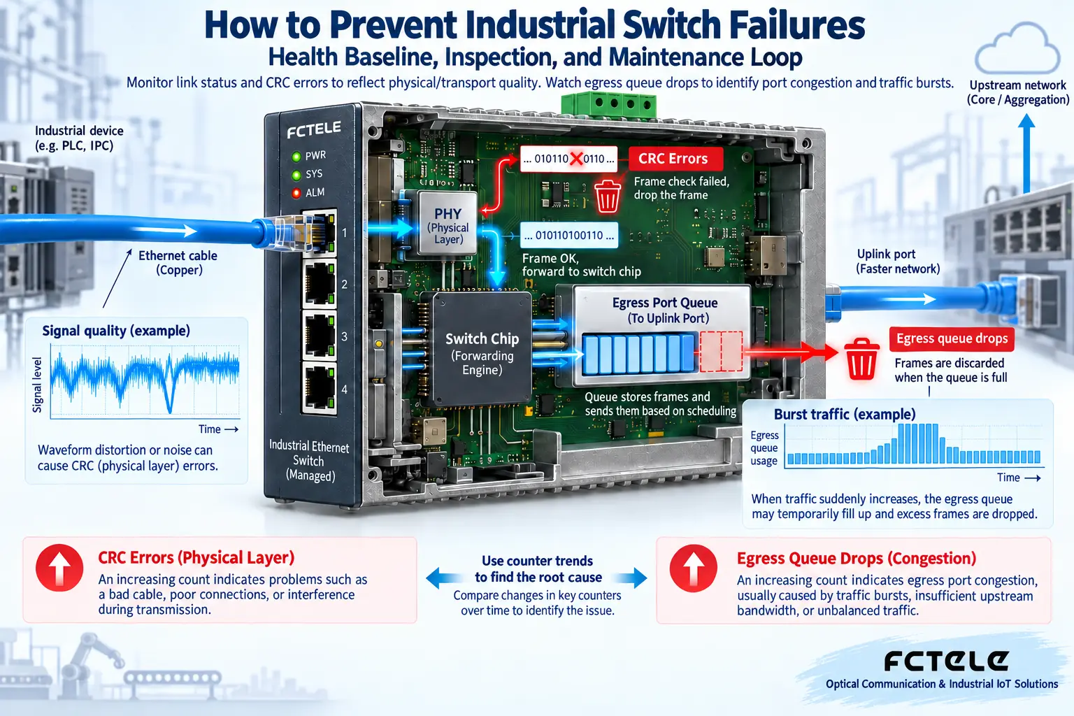
For example, a group of cameras increases bitrate at the same moment; the average traffic over several minutes is still not high, but the instantaneous burst may fill the uplink queue. If CRC has not increased noticeably while egress discards rise, check peak load and uplink planning. If errors are concentrated on one cable and are related to the operation of variable-frequency equipment, first keep a time-sequence record, then have qualified personnel check cabling and interference resistance conditions. Both should be combined with service symptoms, not just bandwidth percentage.
Physical inspection checks connections and environment, do not disassemble at will
Check rail mounting, wiring terminals, cable stress and bending, and confirm that cables will not pull on ports. Check whether there is dust, condensation, or water ingress in the cabinet, and whether the area around the equipment is blocked by newly added power supplies or other heat sources. Temperature judgment should distinguish ambient temperature from case temperature, and check the actual model’s operating range; a case that feels hot is not a uniform fault criterion.
Cooling maintenance should be carried out according to the structure. Fanless devices dissipate heat through the case and air exchange, so a fan replacement plan cannot be copied directly; only models with fans require checking fan operation and replacement requirements. Cleaning external dust should be scheduled with appropriate shutdown and anti-static measures, and do not spray cleaning liquid into the equipment. Optical interface contamination should be handled with suitable inspection and cleaning tools; do not wipe optical end faces with ordinary cotton balls, and do not look directly into optical ports. When opening the cover or replacing parts is required, follow the manufacturer’s repair process.
The presence of dual power supplies does not mean power supply already has redundancy
If both power inputs come from the same power supply, the same protection circuit, or the same loose connector, they may still fail together. Inspection should map the power sources and protection relationships, and check voltage range, polarity, grounding, and terminal tightening requirements. Live measurement and power operations should be performed by qualified personnel; do not casually unplug cables just to test redundancy.
Feichang Technology managed industrial rail-mounted 10G 4-optical 8-electrical Layer 3 switch official website information lists dual power inputs, providing the conditions for planning backup power. During maintenance, still check the input range, internal selection mechanism, and alarm function according to the actual model; dual inputs do not automatically prove that the upstream is independent, nor can it be inferred that services will have zero interruption under any fault.
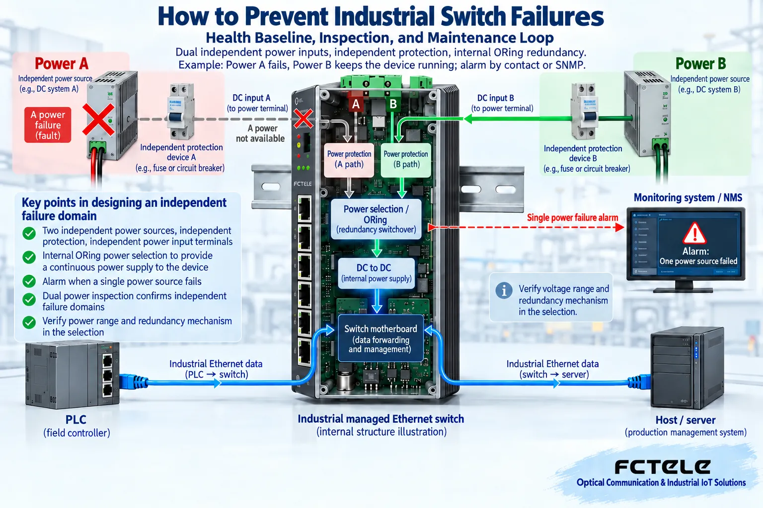
When conditions permit, simulate power failure on each path one by one within an agreed window, observe the voltage on the other side, device status, alarms, and real service communication, then restore and check records. Do not disconnect both paths at the same time to prove redundancy. For equipment that does not support the corresponding test, consult the supplier first and keep design checks and measurement results.
Maintenance plans should be arranged by risk, not by habitual rebooting
Inspection frequency is determined jointly by service importance, environmental changes, historical faults, and manufacturer requirements. Newly commissioned or rewired equipment can be observed more densely, while stable sites can adjust based on records. When equipment is normal, regular rebooting without justification creates extra interruptions and may also clear important counters and logs. Only arrange reboots when there is a known issue, manufacturer recommendation, or clear maintenance item, and save the prior evidence.
Firmware maintenance is also not about upgrading the entire network immediately upon discovering a new version. First read the applicable models, known issues, and upgrade instructions, judge whether it solves the current risk, and verify compatibility on a representative device or test environment. Save versions and configurations, arrange a maintenance window, and prepare a way to restore the original services. One model having dual images does not mean other models do too; do not treat third-party switch recovery commands as a universal practice.
Configuration backup should form a closed loop with restore drills
Every configuration change that passes acceptance should update the controlled backup and port diagram. Backup labels include device identity, version, time, and reason for change, and are stored outside the device. Downloading only to a maintenance computer that may be replaced, or saving only on the device itself, does not constitute a complete recovery arrangement. Accounts and sensitive network information should be access-restricted.
Also check whether the backup can be restored on a compatible device, how the management address is accessed after restoration, and which parameters need to be rechecked. Drills can be performed on a spare device or in a test environment; do not blindly import files into normal production. Saving configuration and service verification are different actions: after a page import succeeds, you still need to test VLAN paths, uplink and terminal services, and the planned alarms and backup paths.
Inspection should ultimately leave an executable handling record
A qualified record should include the inspection object, observation period, normal reference, evidence of change, handling action, and retest result. For example, if a port’s CRC increment becomes larger, first record the service and time, then replace a confirmed short patch cord during the maintenance window; if errors return to normal, record the cable handling and follow-up observation, and do not rush to send the whole unit for repair. If the change continues, narrow the scope along the connection path.
Separate temporary normality from long-term resolution: the retest time should cover the original abnormal trigger conditions, the service owner confirms communication recovery, and the maintainer updates the backup and topology. If the problem exceeds on-site authority, submit the model, version, logs, counter differences, and verified steps to the supplier. Such records are easier to reuse next time, rather than leaving only the sentence “it was fine after a reboot.”
Reference basis: the above Feichang Technology product details are used to define model capabilities;Cisco configuration backup and restore instructions are used to check backup and restore concepts, and specific operations are subject to the actual device manual. The two figures are general principle illustrations and do not represent product photos, measurement results, or a uniform inspection cycle.
Translated from the Chinese technical article. Source first published: 2024-04-19. Source last revised: 2026-10-13T19:28:50+08:00. Read the Chinese source
