


An industrial switch in a smart grid handles communication forwarding, not electrical energy transmission, and not protection decisions. It connects measurement devices, protection and control devices, and monitoring hosts so that information reaches the devices that need it. Whether it is suitable depends on the business type, network timing, environment, and acceptance evidence; it cannot be decided by the words ‘industrial grade’ alone. Normal operation monitoring and substation protection communication have different requirements, so the boundaries should be clarified before selection.
1. Understanding the role from the process of transmitting one measurement value
Suppose a measurement device inside a distribution cabinet collects temperature or current status. The device itself completes measurement, encoding, and protocol processing, then sends data out from its Ethernet port. The switch receives the frame and chooses the egress according to the destination MAC address, VLAN, and port configuration. The monitoring host then interprets the value, displays a curve, or generates an alarm. The switch usually does not understand whether ‘temperature too high’ requires a shutdown; it only carries the communication path within that process.
If the terminal only has an RS485 serial port, the serial cable cannot be plugged directly into an RJ45 network port. A suitable serial server or protocol gateway is needed, and transparent transmission and protocol conversion are not the same thing. The terminal protocol, host protocol, and gateway function must correspond. Seeing a network port indicator light only shows part of the physical state; it does not prove that the monitoring software has received correct data.
2. Not all in-station information is ordinary TCP/IP data
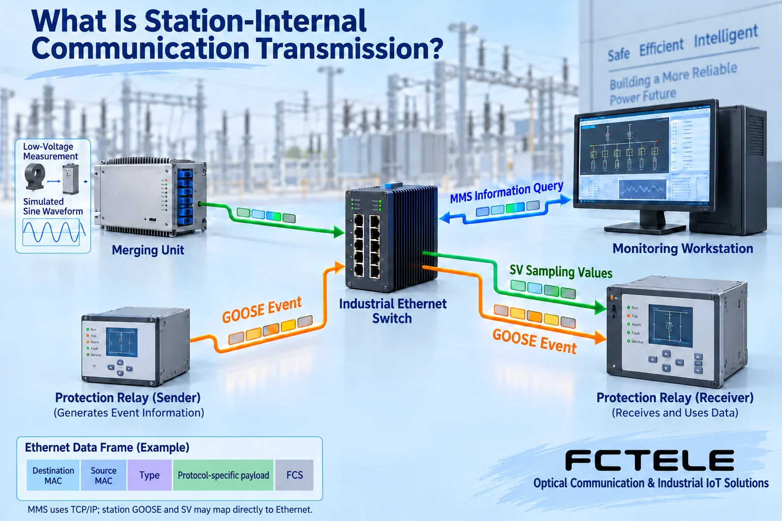
IEC 61850 is a set of information models and communication service specifications for power automation, not a switch model. MMS can be used for information access between clients and servers; common in-station GOOSE is used to transmit event information, and sampled values (SV) are used to send measurement samples. In-station GOOSE and SV have forms that map directly to the Ethernet link layer, so they should not all be described as ordinary TCP connections, and a successful ping alone cannot be used to judge that they are normal.
A protection device is called an IED, that is, an intelligent electronic device. It identifies the corresponding messages and data sets according to the engineering configuration, and the communication network forwards them as required. That a switch supports Layer 2 forwarding does not mean it will automatically modify or understand the protection logic of the IED. Different vendors supporting the same standard still requires checking versions, data models, configurations, and joint debugging results; one cannot assert that mixed networking is necessarily compatible just from the name.
3. Where multicast should be sent, and why it cannot be filtered blindly
Multicast can send the same information to multiple receivers. If the network does not have a suitable forwarding table for a certain type of multicast, it may be forwarded to many ports and occupy links that do not need to receive that information. During planning, list the publishers, subscribers, service VLANs, destination addresses, and allowed egress ports, and check the traffic and protocol requirements, rather than simply enabling a ‘filter’ button.
IGMP is the IP multicast group management protocol. GOOSE in direct Ethernet form cannot necessarily rely on IGMP snooping to obtain a correct forwarding table. Static multicast, related Layer 2 filtering, or other applicable methods should be confirmed according to the switch and engineering design. A configuration error may block the needed messages as well; therefore any change must be verified in an offline joint debugging environment or an approved maintenance arrangement, and trial and error must not be performed on a running protection network.
Traffic competition also introduces queuing. Priority can adjust the transmission order, but it cannot increase the physical egress capacity; continuous SV traffic and event bursts should be evaluated together with monitoring, file transfer, and so on. The transmission time allowed by protection is a system requirement and should be checked from the sending terminal to the receiving terminal; a single switch forwarding specification cannot be treated as the operation time of the entire protection system.

4. Clocks, backup links, and power supply solve different problems
When multiple measurement devices need aligned time, the system clock source and terminal requirements should be checked. PTP, the Precision Time Protocol, can be used for network time synchronization, but whether a switch supports the required clock mode, profile, and accuracy requires specific documentation and testing. If this evidence is not on the web page, one cannot infer support for high-precision time synchronization from support for ordinary management protocols.
A backup link reduces the impact of a failure in a certain line segment, and dual power supplies reduce the impact of a failure in a certain power supply branch. Ordinary ring recovery and specific redundancy mechanisms such as PRP and HSR are different; having enough ports does not mean the device supports these protocols, and an ordinary ring cannot be claimed to be seamless redundancy. A shared cabinet, common power supply, or cables in the same trench may still cause both paths to fail at the same time.
5. Checking application boundaries with Feichang Technology materials
Feichang Technology’s power industry solution introduces directions for data acquisition, operation monitoring, and optical fiber networking. The managed industrial rack-mount 10G four-optical-port, eight-copper-port Layer 3 switch in the product center lists features such as VLAN, QoS, optical and electrical ports, and network management, and can serve as a candidate functional basis for monitoring aggregation. Optical interfaces make it convenient to connect remote cabinets, and management functions help read status, save configurations, and locate link problems.
However, these public descriptions cannot replace substation-specific environmental tests, protection communication compliance, or time synchronization proof. Interface, power supply, temperature, electromagnetic compatibility, and required function documentation should be obtained according to the specific model and delivery version; write the conditions into project acceptance. Do not carry over the old article’s conclusion that ‘all models can satisfy power sites,’ and do not treat other manufacturers’ reference designs as Feichang Technology product certifications.
6. Acceptance should look at what the terminal receives, not just whether the link light is on
In an approved test environment, first check the data between the terminal and the host item by item, then check multicast egress, concurrent traffic, and time stamps; verify power supply and link failure recovery separately, and record device configuration, firmware, topology, port counters, and application logs. A general network engineer should not arbitrarily change protection settings, publish trip messages, or connect on-site test devices; these operations should be arranged by power professionals according to project procedures.
The correct positioning is: the switch provides a manageable, verifiable communication path, the terminal completes measurement and protection logic, and system engineering ensures coordination. Only by separating these three layers of responsibility can suitable equipment be selected for a smart grid, and can a one-time network connectivity test be prevented from being mistaken for protection system acceptance.
Materials and schematic notes
References Feichang Technology power application direction , Feichang Technology Layer 3 switch product information , TI’s GOOSE frame processing reference design and ABB’s explanation of MMS, GOOSE, and SV mapping . The two figures are general mechanism schematics, not on-site measurements, product teardowns, or certification materials.
Translated from the Chinese technical article. Source first published: 2021-07-12. Source last revised: 2026-10-13T11:20:43+08:00. Read the Chinese source
