


A phone can hear sound, but it also needs to be able to set up and release calls
In addition to carrying sound, a telephone system must tell the other side: whether a speech path is idle, who is calling, what the called number is, when to answer, and when to release. No.1 signaling is a type of signaling used in traditional telephone access and interoffice coordination. When upgrading an old system, voice encoding, the E1 line, and call control must all match at the same time; you cannot assume they can interconnect just because the plugs are the same.
Chinese No.1 signaling is related to the multi-frequency compelled mechanism of international R2, but national variants and the implementation of specific switching equipment still need to be checked. This article explains the connection process and digital channel-associated access, and it cannot treat every code of international R2 directly as a configuration table for all Chinese No.1 signaling equipment. Similar names only indicate the technical background; interworking requires actual documents and testing from both sides.
Line signaling manages states, register signaling manages connection information
Line signaling focuses on the state of a speech path, such as seizure, answer, and release. Register signaling focuses on the information needed to set up a call, such as numbers and user category. A register can be understood as a functional unit in switching equipment that temporarily handles connection information, and it is not necessarily a separate external piece of hardware. The two kinds of signaling have different roles, so when troubleshooting you should also look separately at state changes and number interworking.
In terms of transmission form, old systems had different implementations such as DC, in-band single-frequency, and digital line signaling; in terms of direction, forward means sent from the calling side to the called side, and backward means the response in the opposite direction. Direction is determined by the role in a given call, so a physical port cannot be permanently called forward-only. Interface wiring, detection thresholds, and timing must follow the corresponding equipment.
How digital channel-associated signaling corresponds to E1 timeslots
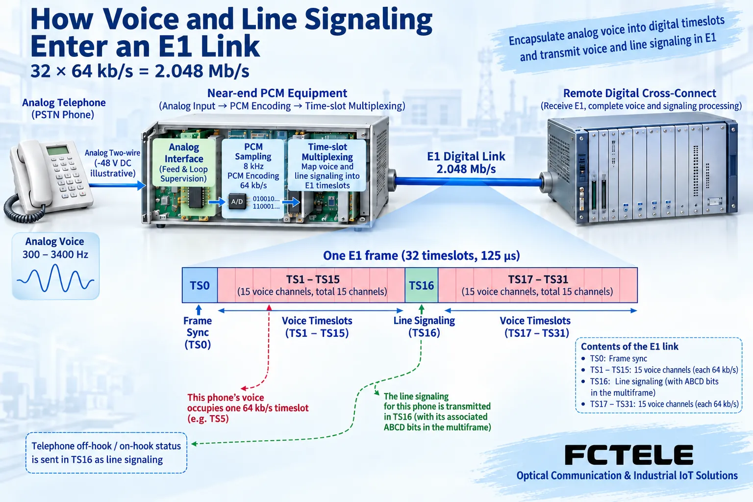
E1 is a digital line of about 2,048,000 bits per second. A common framed E1 divides repeating frames into 32 timeslots numbered TS0 to TS31; a timeslot is a transmission position occupied in turn by time, not 32 separate wires. TS0 carries overhead such as frame alignment; digital channel-associated configurations usually use TS16 for line signaling, and voice is distributed across the remaining 30 service timeslots.
The state information in TS16 is arranged by multiframe and corresponds to the relevant speech paths. Channel-associated emphasizes the association between signaling and a specific speech path, and it cannot be said from this that all signaling is always packed into the same timeslot as voice. It is not accurate for old articles to directly call this arrangement 30 B channels plus a D channel; that name belongs to the PRI access context and cannot replace the CAS line-state bit explanation.
Why does one number interworking require responses from both sides?
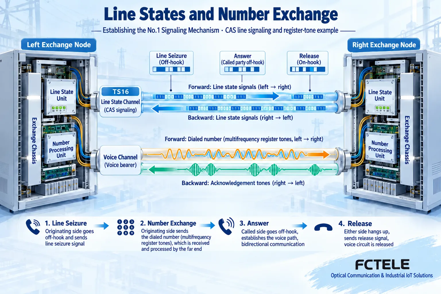
The multi-frequency register mechanism uses combined tones to pass connection information, the receiving side returns a corresponding response, and the sending side then continues processing according to the agreement. In digital access, this kind of in-band information can be transmitted over the corresponding speech path; it has a different responsibility from the TS16 line state. The specific tone codes, groups, and compelled timing are determined by national specifications and equipment configuration, and a single general diagram should not be used to infer a unified code.
A simplified call can be understood as seizure, number interworking, called-side response, answer and conversation, and release. If the line can be seized but the number is not received correctly, it may appear as a state change with call failure; if answer or release coordination has a problem, one-way abnormality may occur or the speech path may not return to idle in time. Actual judgment must be based on records from both sides, not just one indicator light.
What are the boundaries of SS7 and PRI respectively?
SS7 uses a common channel signaling system and controls related services through signaling messages. The relationship between the signaling link and the controlled speech paths is different from traditional channel-associated methods, and service conversion requires switching or gateway functions that support the corresponding protocol. Changing a cable on an E1, or changing a certain state bit of telephone PCM to another value, will not automatically complete conversion between No.1 signaling and SS7.
PRI is the primary rate access of the Integrated Services Digital Network. A common E1 PRI carries the D-channel protocol in TS16, and services such as voice use B channels. It can have a similar line appearance to E1 CAS, but it uses a different control method. Before purchasing, the peer’s requirements should be clearly written as CAS, No.1 signaling, or PRI and its version, not just that 30 telephone lines or one E1 port are needed.
Check specific access with FCC-CS30
In Feichang Technology’s No.1 signaling E1 PCM category, the FCC-CS30 details list 1 to 30 voice accesses, FXS subscriber telephone ports, and an E1 digital interface, and state that the corresponding ABCD codes can be set through the Console. FXS provides the subscriber-side functions needed to connect to ordinary telephone sets; the E1 side works with compatible digital trunk cards or program-controlled switching equipment, and an Ethernet port cannot be used as a substitute.
ABCD are bit names related to line signaling states, and the configuration must match the peer’s agreement; fixed values must not be tried at random. The official website also lists information such as caller ID, alarms, and optional independent network management, and the specific ordering configuration needs to be checked. Caller ID also depends on whether the calling number is passed, how the switching equipment handles it, and whether the telephone terminal supports it; the device name does not guarantee that any line will display it correctly.
Acceptance layer by layer from line to call
First save both sides’ model, version, port impedance, code type, clock source, framing, and signaling configuration, then check E1 link alarms and errors. After the electrical line is stable, check the correspondence between timeslots and telephone numbers, select a small number of speech paths for two-way calls, and observe ringing, answer, two-way sound, release, and re-seizure separately. Expand concurrency gradually, and do not replace full equipment acceptance with one successful call.
If calls cannot be made, first distinguish whether it is loss of frame alignment, inconsistent line state, number interworking failure, or an audio path problem. Record each event and logs from both sides, adjust one variable at a time during the maintenance window, and keep a rollback configuration. The vendor-specific operating reserved parameters in old articles have no model or version basis and cannot be copied as general repair commands into the current switching system.
Write the handover as a record the next maintainer can review
Suppose an old program-controlled switching device needs to use E1 to connect to a remote telephone access point. First confirm that it provides a compatible No.1 or CAS trunk, then choose the telephone-side configuration and number of channels. This is a requirements-understanding example, not a completed customer project. If the peer only has PRI or requires SS7, the corresponding conversion capability should be checked separately instead of forcibly applying ordinary telephone PCM.
The handover record keeps the channel table, wiring identity, line and signaling parameters, normal state baseline, and abnormal test results. In particular, test called party busy, no answer, either end hanging up, and recovery after interruption, and observe whether resources are released. Only when sound, call state, and number information are all correct can it be said that this telephone access link works as expected.
Document note: The principle diagrams have been checked for technical content and are used to explain general mechanisms; they are not product photos or measured records. Specific interfaces, modes, and capabilities are subject to the selected model, version, and on-site verification.
Verification documents: ITU-T Q.400—Q.490: R2 signaling mechanism
Cisco E1 R2 line and register signaling
ITU-T G.704: Synchronous frame structure
ITU-T Q.700: SS7 signaling system
Feichang Technology FCC-CS30 No.1 signaling E1 PCM
Feichang Technology No.1 signaling E1 PCM category
Related technical topics: How to maintain and protect an OEO fiber repeater: two optical paths, local power, and fault location What is an industrial transceiver: interface chips, wireless modules, and complete fiber optic units must be distinguished
Translated from the Chinese technical article. Source first published: 2020-09-03. Source last revised: 2026-10-13T02:05:34+08:00. Read the Chinese source
