


For the management work of a Layer 3 industrial Ethernet switch, you should separate “whether the device can be managed” from “whether services are forwarded correctly.” Being able to log in to the web page only means that this management path is reachable; it cannot prove that all VLANs, routes, next hops, and access rules are normal. Troubleshooting should follow the real path of the service to gather evidence, then make small-scope, rollback-capable changes, rather than restarting the device whenever there is no connectivity.
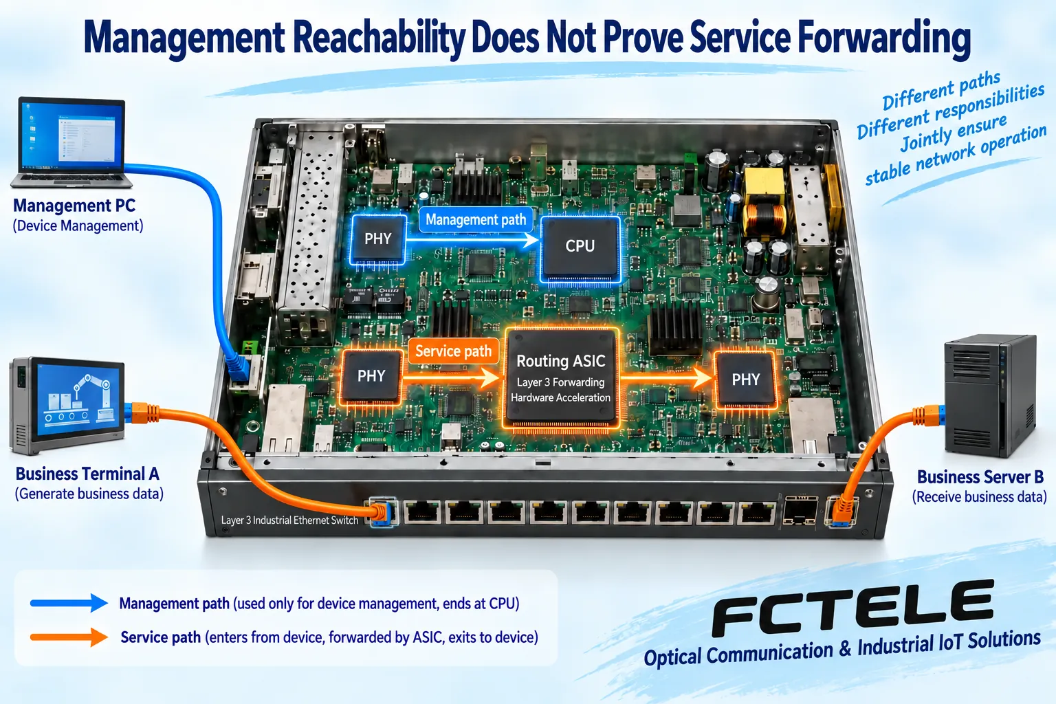
1. Management access and service data take different paths
When a management computer accesses the switch’s management address, the data endpoint is the device’s own management service; when a field terminal accesses a server on another subnet, the data must be forwarded out by the device. The two may pass through different VLANs, rules, and interfaces. The CPU being able to respond to management requests does not mean the service egress is normal; an interruption in management access does not necessarily mean that all hardware forwarding has stopped at the same time.
First confirm whether the fault is a certain service, a certain subnet, or the entire site; record the source, destination, time of occurrence, and whether it is continuous. Do not summarize the phenomenon only as “the network is down.” Divide permissions for management accounts to avoid multiple people modifying the same configuration at the same time; give priority to the secure management methods supported by the delivered model, and do not expose plaintext remote access to untrusted networks.
2. If cross-subnet communication fails, first check reachability status
The terminal needs the correct address, mask, and gateway, and the access port needs to place traffic into the correct Layer 2 scope. The corresponding Layer 3 interface must be in a usable state, and the device also needs a route matching the destination. If these basic conditions are not met, changing queue priority or enabling more management functions will not solve the problem.
After the route table has a path to the destination, you also need to check next-hop resolution and egress. The next hop is the neighboring device to which the packet should currently be handed, not necessarily the final server; IPv4 often establishes the relationship between neighboring IP and MAC through ARP. When resolution fails, you may need to check the local link and configuration, and should not immediately add another default route, which would mask the symptom as a more complex path problem.
Align the ingress, destination path, next hop, access rules, and egress status within the same time window, then check the server’s return path. Ordinary access control rules may allow only one direction, and the terminal or the server’s own protection may also reject requests. Suspicion that the switch is at fault needs supporting evidence; do not draw a conclusion based only on one application timeout.
3. Look at counter changes, not just cumulative totals
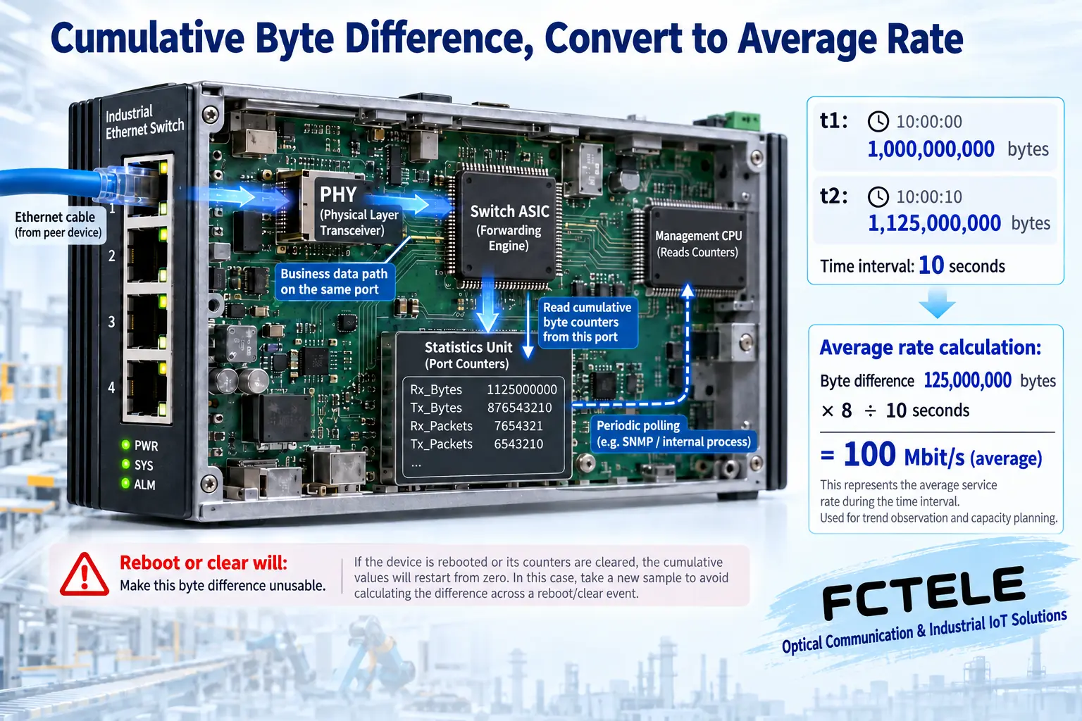
Port statistics usually store cumulative bytes, packets, and various error or discard counts. Comparing the changes between two sampling moments better explains what happened during the fault. A large cumulative error count may come from a long time ago, while a small number of errors that continue to increase currently may also deserve more attention. Interface indexes, actual ports, and measurement directions must first be aligned; do not compare values from two different ports.
In the teaching example, the byte count of the same egress increases by 125,000,000 bytes within 10 seconds. Multiply the change by 8 and divide by 10 to get an average rate of about 100 Mbit/s. It is the average over this period, not the peak, and it is not equal to application effective throughput. If the device restarts, counters are cleared, or counter discontinuity occurs, this difference cannot be directly treated as the real rate; for high-speed ports, you should also check the counter bit width and the tool’s handling method.
4. Distinguish errors, discards, and application timeouts
The causes of link receive errors and egress discards are not the same. The former may be related to physical transmission, the interface, or frames; the latter may also be related to congestion, rules, resources, or model-specific statistical definitions. First read the specific counter definitions, then correlate optical module information, port rate, queues, and logs. You cannot automatically judge that the cable is bad just because you see one “discard.”
A low average port utilization rate also cannot prove that there is no burst queuing. When needed, under authorized conditions, increase sampling or use appropriate packet capture, but the observed traffic copied by port mirroring also has capacity and selection range limits. If the mirror port does not capture packets, it may be an omission of the mirror itself; you cannot assert without cross-checking that the original service did not send anything.
5. How Feichang Technology management functions become maintenance evidence
Feichang Technology Managed industrial rail-type 10G 4-fiber 8-copper Layer 3 switch The details list management access, port statistics, logs, optical module information, and corresponding Layer 3 functions, which can be used to build maintenance records of device status and service paths. Which fields are actually readable, the refresh cycle, and the alarm method should be based on the delivered model, firmware, and manual; third-party MIB definitions cannot prove that every item is supported.
Save configuration backups, time synchronization status, port identifiers, and firmware version together, so that different people can compare the same fault. When log time and packet capture time are inconsistent, first calibrate the time relationship of the evidence to avoid piecing different events into one cause. Do not arbitrarily clear original error records just to improve dashboard numbers.
6. Optimization should be a verified change
After forming a clear hypothesis, change one justified configuration item at a time, and record the service performance and device status before and after the modification. When routes, VLANs, or access rules are involved, arrange an approval window and a rollback plan; do not arbitrarily shut down protocols or expand access permissions in a running control network. A restart may temporarily change the symptom, but it will lose important on-site evidence.
Acceptance should look not only at the management page, but also at whether the originally failed service has recovered, whether the originally restricted service is still restricted, and whether the return path and management channel remain intact. Being able to explain which segment’s status was abnormal, how it was verified, how it was corrected, and how the result was reproduced is more reliable than vaguely saying that the network has been intelligently optimized.
Reference note: Interface counters and discontinuity handling refer to RFC 2863 . The figures are general principle diagrams, the examples are not model measurements, and the specific counter definitions should be checked against the device documentation.
Translated from the Chinese technical article. Source first published: 2024-03-06. Source last revised: 2026-10-13T11:20:43+08:00. Read the Chinese source
